
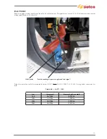


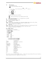


214
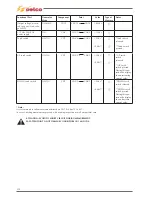
E11
System configuration alarm
uC and DSP board 15.14.415
failed communication, due to
data error.
Origin could be research on
installed software’s incompa-
tibility, hardware problem on
15.14.415 communication
between uC e DSP.
- Control software relea-
se (par.501 pwd 358 set.up
serv).
Repeat download
software:contact service
Selco.
A reset is suggested.
In case the problem persist
repair 15.14.415 pcb.
E13
Communication alarm (FP)
CAN BUS communication with
front panel missing. Could
be also intend as overload
peripheral can-bus. The digi-
tal card doesn’t recognize the
front panel.
- Perform test on front panel.
- If problem remain is sugge-
sted to disconnect all possi-
ble can bus user’s as WU-RC.
Check integrity of cable to
front panel.Perform test and
in case repair digital pcb.
15.14.415.
E14
Program not valid alarm
EEPROM’s error, due to wel-
ding point saved.
- Reset machine ,over write
program if problem persist
repair 15.14.415.
E15
Program not valid alarm
Introduction of new parame-
ters after software download
that doesn’t match with exi-
sting stored program.
- Reset machine then over
write program present.
Control software release
(par.501 pwd 358 set.up serv)
contact service Selco.
- Repair pcb 15.14.415.
E17
Communication alarm
(
μ
P-DSP)
15.14.415 internal failure.
Wrong software download.
Control software release
(par.501 pwd 358 set.up
serv), update software, reset,
15.14.415 repair.
E18
Program not valid alarm
Recall of stored program in
wrong sequence, as program
2T to 4T or AC to DC.
Recall during welding of com-
patible programs. Check sto-
red program. In case overwrite
with new program.
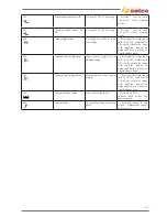
E19
System configuration alarm
- Internal software doesn’t
match.
- Pcb rack 15.14.431 has been
replaced without reset.
- Control software relea-
se (par.501 pwd 358 set.up
serv).
Repeat download software:
contact service Selco.
A reset is suggested.
In case the problem persist
repair 15.14.415 pcb.
E20
Memory fault alarm
EEPROM memory problem
card 15.14.415 failed.
- Reset menu, test 15.14.415,
repair pcb.
E21
Data loss alarm
Wrong data EEPROM rea-
ding,15.14.415 hardware fai-
lure.
H.F. noise presence.
- Reset menu, check for
any h.f. leakage, repair pcb.
15.14.415.
E22
Communication alarm (DSP)
15.14.415 internal failure ,
communication failed betwe-
en uC and DSP.
Test 15.14.415, repair pcb.
E27
Memory fault alarm
(
)
Hardware error clock storing
circuit.
- Test 15.14.415, repaire pcb.
E29
Incompatible measurements
alarm
If MMA set,or after hold on
switch torch the voltage and
current feedback remain at
“0”.
- Perform test on input inver-
ter and pfc power stage.
- Check ouput rectifier diode,
IGBT, hall sensor on card
15.14.431, output filter card.
Summary of Contents for Genesis 1700 AC/DC
Page 1: ...Genesis 1700 AC DC Genesis 2200 AC DC MANUALE DI RIPARAZIONE REPAIR MANUAL ...
Page 51: ...161 PFC S POWER COMPONENTS D11 IG1 IG2 D1 D7 CN3 M1 CN4 CN5 CN8 CN7 M2 CN6 ...
Page 52: ...162 PFC STAGE LEDS INDICATIONS PFC s POWER COMPONENTS L2 L1 IG1 IG2 D1 CN6 D7 D11 ...
Page 54: ...164 INVERTER STAGE CN3 M1 CN4 CN5 CN8 CN7 M2 Inverter IMS power module ...
Page 62: ...172 15 Remove pcb T3 PFC s POWER COMPONENTS IG1 IG2 D1 NTC1 Unscrew torque screw at 2 2N mt ...
Page 64: ...174 DIODES AND PFC IGBT ORIENTATION Landmark for assembling ...
Page 67: ...177 12 4 Thermic caps inverter side NTC1 T3 CN11 ...
Page 69: ...179 12 5 Thermic caps secondary side T1 T2 15 14 434 CN3 CN2 ...
Page 74: ...184 15 14 439 15 14 42901 L3 L4 L1 L2 ...
Page 75: ...185 Gas valve flow chart signal Pipe 38 39 ...
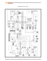
Page 79: ...189 CN6 15 14 415 CN3 15 14 431 FLAT A FLAT B Inverter commands Boost commands ...
Page 80: ...190 By pass relais flow chart Gas valve ELVI Fan M1 and M2 command signal ...
Page 81: ...191 HF command signal AC command signal Torch switch buttons signals ...
Page 88: ...198 HF pulse in TIG AC HF pulse in TIG DC ...
Page 114: ...224 GENESIS 2200 AC DC FP279 ...
Page 115: ...225 GENESIS 1700 AC DC FP216 ...
Page 116: ...226 GENESIS 2200 AC DC FP216 ...
Page 118: ...228 20 CONNETTORI CONNECTORS GENESIS 1700 AC DC FP279 GENESIS 2200 AC DC FP279 ...
Page 119: ...229 GENESIS 1700 AC DC FP216 GENESIS 2200 AC DC FP216 ...
Page 122: ...232 55 08 022 55 08 023 GENESIS 1700 AC DC FP216 GENESIS 2200 AC DC FP216 ...


