


Store the selected parameter in the 7 segment display
by pressing button (2)
.
Save and exit the current screen by pressing button (4)
.
Default
I1
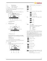
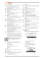
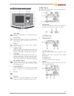
3.7 Interface personalisation
Allows the parameters to be customized on the main menu.
500
Allows the selection of the required graphic interface:
XE (Easy Mode)
XA (Advanced Mode)
XP (Professional Mode)
XE
XA
XP
PROCESS
MMA
TIG DC
TIG AC
MMA
TIG DC
TIG AC
MMA
TIG DC
TIG AC
PARAMETER
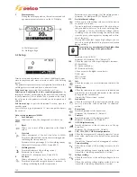
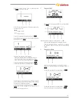
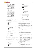
3.8 Lock/unlock
Allows all the settings to be locked from the control panel with
a security password.
Enter set-up by pressing the encoder key for at least 5 seconds.
Select the required parameter (551) by rotating the encoder
until it is displayed within the central quadrant.
Activate the regulation of the selected parameter by pressing the
encoder button.
Set a numerical code (password) by rotating the encoder.
Confirm the change made by pressing the encoder button.
Save and exit the current screen by pressing button (4)
.
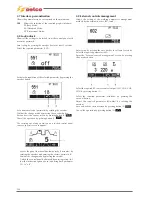
The carrying out of any operation on a locked control panel
causes a special screen to appear.
- Access the panel functionalities temporarily (5 minutes) by
rotating the encoder and entering the correct password.
Confirm the change made by pressing encoder button.
- Unlock the control panel definitively by entering set-up (fol-
low the instructions given above) and bring back parameter
551 to “off”.
Confirm the changes made by pressing button (4)
.
131
Summary of Contents for Genesis 1700 AC/DC
Page 1: ...Genesis 1700 AC DC Genesis 2200 AC DC MANUALE DI RIPARAZIONE REPAIR MANUAL ...
Page 51: ...161 PFC S POWER COMPONENTS D11 IG1 IG2 D1 D7 CN3 M1 CN4 CN5 CN8 CN7 M2 CN6 ...
Page 52: ...162 PFC STAGE LEDS INDICATIONS PFC s POWER COMPONENTS L2 L1 IG1 IG2 D1 CN6 D7 D11 ...
Page 54: ...164 INVERTER STAGE CN3 M1 CN4 CN5 CN8 CN7 M2 Inverter IMS power module ...
Page 62: ...172 15 Remove pcb T3 PFC s POWER COMPONENTS IG1 IG2 D1 NTC1 Unscrew torque screw at 2 2N mt ...
Page 64: ...174 DIODES AND PFC IGBT ORIENTATION Landmark for assembling ...
Page 67: ...177 12 4 Thermic caps inverter side NTC1 T3 CN11 ...
Page 69: ...179 12 5 Thermic caps secondary side T1 T2 15 14 434 CN3 CN2 ...
Page 74: ...184 15 14 439 15 14 42901 L3 L4 L1 L2 ...
Page 75: ...185 Gas valve flow chart signal Pipe 38 39 ...
Page 79: ...189 CN6 15 14 415 CN3 15 14 431 FLAT A FLAT B Inverter commands Boost commands ...
Page 80: ...190 By pass relais flow chart Gas valve ELVI Fan M1 and M2 command signal ...
Page 81: ...191 HF command signal AC command signal Torch switch buttons signals ...
Page 88: ...198 HF pulse in TIG AC HF pulse in TIG DC ...
Page 114: ...224 GENESIS 2200 AC DC FP279 ...
Page 115: ...225 GENESIS 1700 AC DC FP216 ...
Page 116: ...226 GENESIS 2200 AC DC FP216 ...
Page 118: ...228 20 CONNETTORI CONNECTORS GENESIS 1700 AC DC FP279 GENESIS 2200 AC DC FP279 ...
Page 119: ...229 GENESIS 1700 AC DC FP216 GENESIS 2200 AC DC FP216 ...
Page 122: ...232 55 08 022 55 08 023 GENESIS 1700 AC DC FP216 GENESIS 2200 AC DC FP216 ...