


213
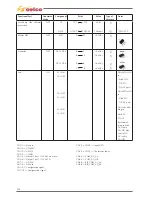
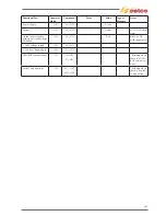
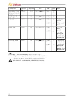
14) ALARMS TROUBLESHOOTING
Alarms
Description
Possible cause
Checks
E01
Temperature alarm 1
NTC primary side alarm.
- If the alarm is tripped for a
temperature rise due to extra
duty cycle working time at
high currents, wait for the coo-
ling of the generator. With the
generator turned on, the fans
work to speed up the cooling
of the generator.
- If the alarm is present just
switching on generator (status
"cold") the NTC1 is defecti-
ve or a cable connection is
disconnected.
See "Test on Primary Thermic
sensor ”.
E02
Temperature alarm 2
Thermic T1 primary side
alarm.
- If the alarm is tripped for a
temperature rise due to extra
duty cycle working time at
high currents, wait for the coo-
ling of the generator. With the
generator turned on, the fans
work to speed up the cooling
of the generator.
- If the alarm is present just
switching on generator (status
"cold") the T1 is defective or
a cable connection is discon-
nected.
See "Test on Primary Thermic
sensor ”.
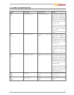
E03
Temperature alarm 3
NTC2 and T2 secondary side
alarm.
- If the alarm is tripped for a
temperature rise due to extra
duty cycle working time at
high currents, wait for the coo-
ling of the generator. With the
generator turned on, the fans
work to speed up the cooling
of the generator.
- If the alarm is present just
switching on generator (status
"cold") the NTC2 or T2 are
defective or a cable connec-
tion is disconnected.
See "Test on card AC 15.14.434 ”.
E06
PFC alarm
A problem occured in PFC
stage.
- Perform checks on inverter
and PFC stage.
E10
Inverter alarm
A problem occured in inverter
stage.
- Perform checks on inverter
stage.
Summary of Contents for Genesis 1700 AC/DC
Page 1: ...Genesis 1700 AC DC Genesis 2200 AC DC MANUALE DI RIPARAZIONE REPAIR MANUAL ...
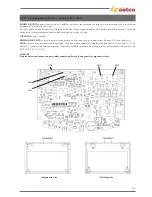
Page 51: ...161 PFC S POWER COMPONENTS D11 IG1 IG2 D1 D7 CN3 M1 CN4 CN5 CN8 CN7 M2 CN6 ...
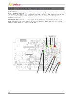
Page 52: ...162 PFC STAGE LEDS INDICATIONS PFC s POWER COMPONENTS L2 L1 IG1 IG2 D1 CN6 D7 D11 ...
Page 54: ...164 INVERTER STAGE CN3 M1 CN4 CN5 CN8 CN7 M2 Inverter IMS power module ...
Page 62: ...172 15 Remove pcb T3 PFC s POWER COMPONENTS IG1 IG2 D1 NTC1 Unscrew torque screw at 2 2N mt ...
Page 64: ...174 DIODES AND PFC IGBT ORIENTATION Landmark for assembling ...
Page 67: ...177 12 4 Thermic caps inverter side NTC1 T3 CN11 ...
Page 69: ...179 12 5 Thermic caps secondary side T1 T2 15 14 434 CN3 CN2 ...
Page 74: ...184 15 14 439 15 14 42901 L3 L4 L1 L2 ...
Page 75: ...185 Gas valve flow chart signal Pipe 38 39 ...
Page 79: ...189 CN6 15 14 415 CN3 15 14 431 FLAT A FLAT B Inverter commands Boost commands ...
Page 80: ...190 By pass relais flow chart Gas valve ELVI Fan M1 and M2 command signal ...
Page 81: ...191 HF command signal AC command signal Torch switch buttons signals ...
Page 88: ...198 HF pulse in TIG AC HF pulse in TIG DC ...
Page 114: ...224 GENESIS 2200 AC DC FP279 ...
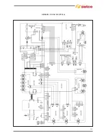
Page 115: ...225 GENESIS 1700 AC DC FP216 ...
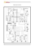
Page 116: ...226 GENESIS 2200 AC DC FP216 ...
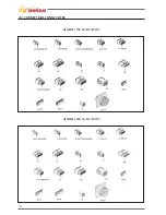
Page 118: ...228 20 CONNETTORI CONNECTORS GENESIS 1700 AC DC FP279 GENESIS 2200 AC DC FP279 ...
Page 119: ...229 GENESIS 1700 AC DC FP216 GENESIS 2200 AC DC FP216 ...
Page 122: ...232 55 08 022 55 08 023 GENESIS 1700 AC DC FP216 GENESIS 2200 AC DC FP216 ...


