


114
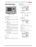
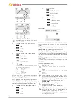
USE AND ROUTINE MAINTENANCE OF POWER SOURCES AND ACCESSORIES, TECHNICAL DATES
Use and routine maintenance (excerpt from the "Instructions for use" manual provided with each power source).
1 WARNING
Before performing any operation on the machine,
make sure that you have thoroughly read and
understood the contents of this booklet.
Do not perform modifications or maintenance
operations which are not prescribed.
The manufacturer cannot be held responsible for damages to
persons or property caused by misuse or non-application of the
contents of this booklet by the user.
Please consult qualified personnel if you have any
doubts or difficulties in using the equipment.
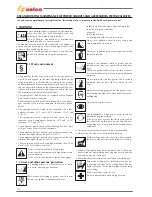
1.1 Work environment
• All equipment shall be used exclusively for the operations for
which it was designed, in the ways and ranges stated on the
rating plate and/or in this booklet, according to the national
and international directives regarding safety. Other uses than
the one expressly declared by the manufacturer shall be con-
sidered totally inappropriate and dangerous and in this case
the manufacturer disclaims all responsibility.
• This equipment shall be used for professional applications
only, in industrial environments.
The manufacturer shall not be held responsible for any dam-
ages caused by the use of the equipment in domestic environ-
ments.
• The equipment must be used in environments with a tem-
perature between -10°C and +40°C (b14°F and
+104°F).
The equipment must be transported and stored in envi-
ronments with a temperature between -25°C and +55°C
(between -13°F and 131°F).
• The equipment must be used in environments free from dust,
acid, gas or any other corrosive substances.
• The equipment shall not be used in environments with a rela-
tive humidity higher than 50% at 40°C (104°F).
The equipment shall not be used in environments with a rela-
tive humidity higher than 90% at 20°C (68°F).
• The system must not be used at an higher altitude than 2,000
metres (6,500 feet) above sea level.
Do not use this machine to defrost pipes.
Do not use this equipment to charge batteries and/
or accumulators.
Do not use this equipment to jump-start engines.
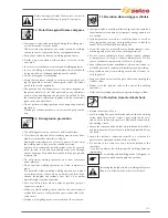
1.2 User's and other persons' protection
The welding process is a noxious source of radia-
tion, noise, heat and gas emissions.
Wear protective clothing to protect your skin from
the arc rays, sparks or incandescent metal.
Clothes must cover the whole body and must be:
- intact and in good conditions
-
fireproof
- insulating and dry
- well-fitting and without cuffs or turn-ups
Always use regulation shoes that are strong and
ensure insulation from water.
Always use regulation gloves ensuring electrical and
thermal insulation.
Position a fire-retardant shield to protect the sur-
rounding area from rays, sparks and incandescent
slags.
Advise any person in the area not to stare at the arc
or at the incandescent metal and to get an adequate
protection.
Wear masks with side face guards and a suitable
protection filter (at least NR10 or above) for the
eyes.
Always wear safety goggles with side guards, espe-
cially during the manual or mechanical removal of
welding slag.
Do not wear contact lenses!.
Use headphones if dangerous noise levels are
reached during the welding.
lf the noise level exceeds the limits prescribed by
law, delimit the work area and make sure that any-
one getting near it is protected with headphones or
earphones.
• The systems must not undergo any kind of modification.
• Always keep the side covers closed while welding.
Avoid touching items that have just been welded:
the heat could cause serious burning or scorching.
• Follow all the precautions described above also in all opera-
tions carried out after welding since slag may detach from the
items while they are cooling off.
• Check that the torch is cold before working on or maintaining it.
Ensure the cooling unit is switched off before dis-
connecting the pipes of the cooling liquid. The hot
liquid coming out of the pipes might cause burning
or scorching.
Keep a first aid kit ready for use.
Do not underestimate any burning or injury.
Summary of Contents for Genesis 1700 AC/DC
Page 1: ...Genesis 1700 AC DC Genesis 2200 AC DC MANUALE DI RIPARAZIONE REPAIR MANUAL ...
Page 51: ...161 PFC S POWER COMPONENTS D11 IG1 IG2 D1 D7 CN3 M1 CN4 CN5 CN8 CN7 M2 CN6 ...
Page 52: ...162 PFC STAGE LEDS INDICATIONS PFC s POWER COMPONENTS L2 L1 IG1 IG2 D1 CN6 D7 D11 ...
Page 54: ...164 INVERTER STAGE CN3 M1 CN4 CN5 CN8 CN7 M2 Inverter IMS power module ...
Page 62: ...172 15 Remove pcb T3 PFC s POWER COMPONENTS IG1 IG2 D1 NTC1 Unscrew torque screw at 2 2N mt ...
Page 64: ...174 DIODES AND PFC IGBT ORIENTATION Landmark for assembling ...
Page 67: ...177 12 4 Thermic caps inverter side NTC1 T3 CN11 ...
Page 69: ...179 12 5 Thermic caps secondary side T1 T2 15 14 434 CN3 CN2 ...
Page 74: ...184 15 14 439 15 14 42901 L3 L4 L1 L2 ...
Page 75: ...185 Gas valve flow chart signal Pipe 38 39 ...
Page 79: ...189 CN6 15 14 415 CN3 15 14 431 FLAT A FLAT B Inverter commands Boost commands ...
Page 80: ...190 By pass relais flow chart Gas valve ELVI Fan M1 and M2 command signal ...
Page 81: ...191 HF command signal AC command signal Torch switch buttons signals ...
Page 88: ...198 HF pulse in TIG AC HF pulse in TIG DC ...
Page 114: ...224 GENESIS 2200 AC DC FP279 ...
Page 115: ...225 GENESIS 1700 AC DC FP216 ...
Page 116: ...226 GENESIS 2200 AC DC FP216 ...
Page 118: ...228 20 CONNETTORI CONNECTORS GENESIS 1700 AC DC FP279 GENESIS 2200 AC DC FP279 ...
Page 119: ...229 GENESIS 1700 AC DC FP216 GENESIS 2200 AC DC FP216 ...
Page 122: ...232 55 08 022 55 08 023 GENESIS 1700 AC DC FP216 GENESIS 2200 AC DC FP216 ...