


160
BOARD FUNCTION:
this card contains all the power components necessary for complete inverter and PFC group.
All the components, three Isotop for PFC stage and one module IMS(Insulated Metal Substrate) for inverter stage ensure total
ground isolation with coolers and reduced EMI disturbances. The PFC stage control the Vbus status at 375vdc. The inverter is Zero
Voltage Switching type with current regulation made by Phase Shifting. Vbus reference and the main transformer current are con-
trolled from analog card 15.14.419 that isolated and derate the signal in order to transmit relative value to digital card 15.14.415
and this one back to inverter and pfc group. A DC capacitors link is present.
LOCATION:
central left side. Electrically speaking it is connect between the main power transformer and receive the power from
input inductance.
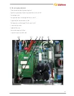
DISMANTLING NOTE:
remove screws on power components and cables from input stage and transformer, ref. to following photos
sequence. Pay attention on dismounting and assembling to the right connection of winding from input stage and to pass trough
the TA one of the two transformer leads. It’s recommended lead mark for properly assembling. The flat cables need to be removed
since rack pcb 15.14.419-415,remain otherwise fixed on inverter groupt. Remove also CN6.
The dismantling could be easier removing the bottom aluminium part.
NOTE:
it is supply as kit togheter with power module just soldered on it and separately additional Isotop. Pay attention on dismount-
ing and assembling to the right connection of leads from input stage and to pass trough the TA one of the two transformer leads.
The power components are assembled on heat skin with use of thermic grease(thermic composed). Pcb. or power components not
available separately.
12.2) Power inverter-pfc pcb ref. 15.18.035 (schede 15.14.422 e 15.14.423)
Summary of Contents for Genesis 1700 AC/DC
Page 1: ...Genesis 1700 AC DC Genesis 2200 AC DC MANUALE DI RIPARAZIONE REPAIR MANUAL ...
Page 51: ...161 PFC S POWER COMPONENTS D11 IG1 IG2 D1 D7 CN3 M1 CN4 CN5 CN8 CN7 M2 CN6 ...
Page 52: ...162 PFC STAGE LEDS INDICATIONS PFC s POWER COMPONENTS L2 L1 IG1 IG2 D1 CN6 D7 D11 ...
Page 54: ...164 INVERTER STAGE CN3 M1 CN4 CN5 CN8 CN7 M2 Inverter IMS power module ...
Page 62: ...172 15 Remove pcb T3 PFC s POWER COMPONENTS IG1 IG2 D1 NTC1 Unscrew torque screw at 2 2N mt ...
Page 64: ...174 DIODES AND PFC IGBT ORIENTATION Landmark for assembling ...
Page 67: ...177 12 4 Thermic caps inverter side NTC1 T3 CN11 ...
Page 69: ...179 12 5 Thermic caps secondary side T1 T2 15 14 434 CN3 CN2 ...
Page 74: ...184 15 14 439 15 14 42901 L3 L4 L1 L2 ...
Page 75: ...185 Gas valve flow chart signal Pipe 38 39 ...
Page 79: ...189 CN6 15 14 415 CN3 15 14 431 FLAT A FLAT B Inverter commands Boost commands ...
Page 80: ...190 By pass relais flow chart Gas valve ELVI Fan M1 and M2 command signal ...
Page 81: ...191 HF command signal AC command signal Torch switch buttons signals ...
Page 88: ...198 HF pulse in TIG AC HF pulse in TIG DC ...
Page 114: ...224 GENESIS 2200 AC DC FP279 ...
Page 115: ...225 GENESIS 1700 AC DC FP216 ...
Page 116: ...226 GENESIS 2200 AC DC FP216 ...
Page 118: ...228 20 CONNETTORI CONNECTORS GENESIS 1700 AC DC FP279 GENESIS 2200 AC DC FP279 ...
Page 119: ...229 GENESIS 1700 AC DC FP216 GENESIS 2200 AC DC FP216 ...
Page 122: ...232 55 08 022 55 08 023 GENESIS 1700 AC DC FP216 GENESIS 2200 AC DC FP216 ...


