


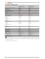


227
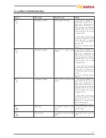
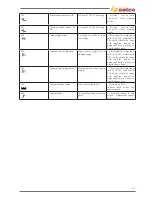
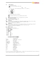
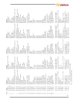
Filo N°/
n° Wire
Descrizione
Description
U
Fase U
Phase U
V
Fase V
Phase V
15
+15Vdc sonda HALL
+15Vdc HALL sensor
16
-15Vdc sonda HALL
-15Vdc HALL sensor
17
Iout sonda HALL
Iout HALL sensor
18
GND_sec
GND_sec
19
Vout+
Vout+
20
NTC1/1
NTC1/1
21
NTC1/2
NTC1/2
22
Termico T3/1
Thermal Protection T3/1
23
Termico T3/2
Thermal Protection T3/2
38
Comando elettrovalvola
Solenoid Valve command
39
+24Vdc elettrovalvola
+24Vdc solenoid valve
40
0_24Vdc comando relè pre-carica
0_24Vdc relay pre-load command
41
+24Vdc comando relè pre-carica
+24Vdc relay pre-load command
42
Comando ventilatore scheda di potenza
Power supply board fan command
43
GND_Comando ventilatore scheda di potenza GND_Power supply board fan command
51
Fase U
Phase U
53
Fase V
Phase V
61
+Vbus
+Vbus
63
0_Vbus
0_Vbus
64
+Vbus
+Vbus
66
0_Vbus
0_Vbus
70
S+ potenza di sovrapposizione
S+ superimposition power
72
S- potenza di sovrapposizione
S- superimposition power
74
Sout potenza di sovrapposizione
Sout siperimpotion power
81
Comunicazione I2C
I2C communication
82
Comunicazione I2C
I2C communication
83
+15Vdc_sec
+15Vdc_sec
84
GND_sec
GND_sec
85
Comando AC
AC command
86
Termico T1/1
Thermal protection T1/1
90
Alimentazione circuito di sovrapposizione
Superimposition circuit power supply
93
Alimentazione circuito di sovrapposizione
Superimposition circuit power supply
94
Alimentazione circuito di sovrapposizione
Superimposition circuit power supply
96
Alimentazione circuito di sovrapposizione
Superimposition circuit power supply
Summary of Contents for Genesis 1700 AC/DC
Page 1: ...Genesis 1700 AC DC Genesis 2200 AC DC MANUALE DI RIPARAZIONE REPAIR MANUAL ...
Page 51: ...161 PFC S POWER COMPONENTS D11 IG1 IG2 D1 D7 CN3 M1 CN4 CN5 CN8 CN7 M2 CN6 ...
Page 52: ...162 PFC STAGE LEDS INDICATIONS PFC s POWER COMPONENTS L2 L1 IG1 IG2 D1 CN6 D7 D11 ...
Page 54: ...164 INVERTER STAGE CN3 M1 CN4 CN5 CN8 CN7 M2 Inverter IMS power module ...
Page 62: ...172 15 Remove pcb T3 PFC s POWER COMPONENTS IG1 IG2 D1 NTC1 Unscrew torque screw at 2 2N mt ...
Page 64: ...174 DIODES AND PFC IGBT ORIENTATION Landmark for assembling ...
Page 67: ...177 12 4 Thermic caps inverter side NTC1 T3 CN11 ...
Page 69: ...179 12 5 Thermic caps secondary side T1 T2 15 14 434 CN3 CN2 ...
Page 74: ...184 15 14 439 15 14 42901 L3 L4 L1 L2 ...
Page 75: ...185 Gas valve flow chart signal Pipe 38 39 ...
Page 79: ...189 CN6 15 14 415 CN3 15 14 431 FLAT A FLAT B Inverter commands Boost commands ...
Page 80: ...190 By pass relais flow chart Gas valve ELVI Fan M1 and M2 command signal ...
Page 81: ...191 HF command signal AC command signal Torch switch buttons signals ...
Page 88: ...198 HF pulse in TIG AC HF pulse in TIG DC ...
Page 114: ...224 GENESIS 2200 AC DC FP279 ...
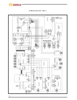
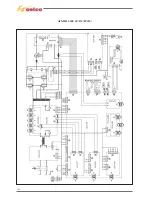
Page 115: ...225 GENESIS 1700 AC DC FP216 ...
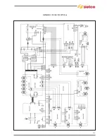
Page 116: ...226 GENESIS 2200 AC DC FP216 ...
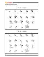
Page 118: ...228 20 CONNETTORI CONNECTORS GENESIS 1700 AC DC FP279 GENESIS 2200 AC DC FP279 ...
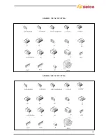
Page 119: ...229 GENESIS 1700 AC DC FP216 GENESIS 2200 AC DC FP216 ...
Page 122: ...232 55 08 022 55 08 023 GENESIS 1700 AC DC FP216 GENESIS 2200 AC DC FP216 ...