


Save all the current settings on the selected program by
pressing button (3)
.
Introduce a description of the program.
- Select the required letter by rotating the encoder.
- Store the selected letter by pressing the encoder.
- Cancel the last letter by pressing button (1)
Cancel the operation by pressing button (2)
.
Confirm the operation by pressing button (3)
.
The storage of a new program on an already occupied
memory location requires cancellation of the memory
location by an obligatory procedure.
Cancel the operation by pressing button (2)
.
Remove the selected program by pressing button (1)
.
Resume the storage procedure.
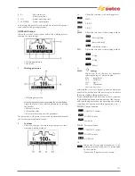
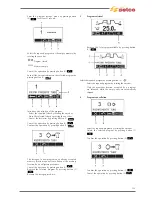
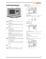
3 Program
retrieval
Retrieve the 1st program available by pressing button
.
Select the required program by pressing button
.
Select the required program by rotating the encoder.
Only the memories location occupied by a program
are retrieved, while the empty ones are automatically
skipped.
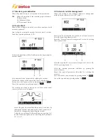
4 Program
cancellation
Enter the “Program cancellation” screen by pressing the
button for at least 1 seconds.
Select the required program by rotating the encoder.
Delete the selected program by pressing button (1)
.
Confirm the operation by pressing button (2)
.
Confirm the operation by pressing button (1)
.
Cancel the operation by pressing button (2)
.
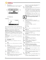
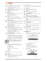
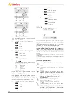
3.6 Interface personalisation
1
7 segment display personalisation
Enter set-up by pressing the encoder button for at least
5 seconds.
Select the required parameter by rotating the encoder
until it is displayed within the central quadrant (5).
130
Summary of Contents for Genesis 1700 AC/DC
Page 1: ...Genesis 1700 AC DC Genesis 2200 AC DC MANUALE DI RIPARAZIONE REPAIR MANUAL ...
Page 51: ...161 PFC S POWER COMPONENTS D11 IG1 IG2 D1 D7 CN3 M1 CN4 CN5 CN8 CN7 M2 CN6 ...
Page 52: ...162 PFC STAGE LEDS INDICATIONS PFC s POWER COMPONENTS L2 L1 IG1 IG2 D1 CN6 D7 D11 ...
Page 54: ...164 INVERTER STAGE CN3 M1 CN4 CN5 CN8 CN7 M2 Inverter IMS power module ...
Page 62: ...172 15 Remove pcb T3 PFC s POWER COMPONENTS IG1 IG2 D1 NTC1 Unscrew torque screw at 2 2N mt ...
Page 64: ...174 DIODES AND PFC IGBT ORIENTATION Landmark for assembling ...
Page 67: ...177 12 4 Thermic caps inverter side NTC1 T3 CN11 ...
Page 69: ...179 12 5 Thermic caps secondary side T1 T2 15 14 434 CN3 CN2 ...
Page 74: ...184 15 14 439 15 14 42901 L3 L4 L1 L2 ...
Page 75: ...185 Gas valve flow chart signal Pipe 38 39 ...
Page 79: ...189 CN6 15 14 415 CN3 15 14 431 FLAT A FLAT B Inverter commands Boost commands ...
Page 80: ...190 By pass relais flow chart Gas valve ELVI Fan M1 and M2 command signal ...
Page 81: ...191 HF command signal AC command signal Torch switch buttons signals ...
Page 88: ...198 HF pulse in TIG AC HF pulse in TIG DC ...
Page 114: ...224 GENESIS 2200 AC DC FP279 ...
Page 115: ...225 GENESIS 1700 AC DC FP216 ...
Page 116: ...226 GENESIS 2200 AC DC FP216 ...
Page 118: ...228 20 CONNETTORI CONNECTORS GENESIS 1700 AC DC FP279 GENESIS 2200 AC DC FP279 ...
Page 119: ...229 GENESIS 1700 AC DC FP216 GENESIS 2200 AC DC FP216 ...
Page 122: ...232 55 08 022 55 08 023 GENESIS 1700 AC DC FP216 GENESIS 2200 AC DC FP216 ...