


199
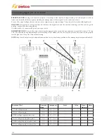
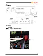
12.11) Output module AC-DC driver pcb ref. 15.14.434
BOARD FUNCTION:
this card realize the final gate’s signal for both power switch of ac-dc module. This card is informed about
which bridge switch-on from digital card.
Internal circuit in order to clamp overvoltage during ac-dc switching.
Receive also the secondary thermostat and NTC ,and transmit the thermal status via bus board to the analogic card then to the
digital control card.
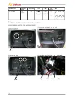
LOCATION:
right upper section, the pc board has got a trapezoidal shaping.
DISMANTLING NOTE:
remove connectors CN1 to CN4 and wire on C1. Four screws fix the pcb on aluminium frame. Different
lay out connectors avoid wrong replacement .
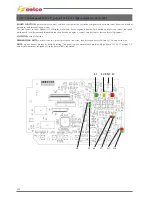
NOTE:
two led shown which diagonal is switched, if DC+/DC- or blinking in case of AC welding.
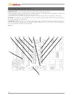
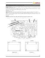
MF1
TR2
TR1
Z4
D8
Z9
Z10
Z5 Z7 Z6 D9
L2
L3
TR3
TR4
Z8
Z11
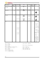
Functional Part
Generator/
Mode
Component
Point Value
Type
of
Measure
Notes
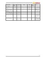
Diodes
OFF
Z4
Z5
Z6
Z7
Z8
Z9
Z10
Z11
D8
D9
A
K
A
K
A
K
A
K
A
K
A
K
A
K
A
K
A
K
A
K
+0.7Vdc
+0.7Vdc
+0.7Vdc
+0.7Vdc
+0.6Vdc
+0.6Vdc
+0.6Vdc
+0.6Vdc
+0.5Vdc
+0.5Vdc
Summary of Contents for Genesis 1700 AC/DC
Page 1: ...Genesis 1700 AC DC Genesis 2200 AC DC MANUALE DI RIPARAZIONE REPAIR MANUAL ...
Page 51: ...161 PFC S POWER COMPONENTS D11 IG1 IG2 D1 D7 CN3 M1 CN4 CN5 CN8 CN7 M2 CN6 ...
Page 52: ...162 PFC STAGE LEDS INDICATIONS PFC s POWER COMPONENTS L2 L1 IG1 IG2 D1 CN6 D7 D11 ...
Page 54: ...164 INVERTER STAGE CN3 M1 CN4 CN5 CN8 CN7 M2 Inverter IMS power module ...
Page 62: ...172 15 Remove pcb T3 PFC s POWER COMPONENTS IG1 IG2 D1 NTC1 Unscrew torque screw at 2 2N mt ...
Page 64: ...174 DIODES AND PFC IGBT ORIENTATION Landmark for assembling ...
Page 67: ...177 12 4 Thermic caps inverter side NTC1 T3 CN11 ...
Page 69: ...179 12 5 Thermic caps secondary side T1 T2 15 14 434 CN3 CN2 ...
Page 74: ...184 15 14 439 15 14 42901 L3 L4 L1 L2 ...
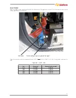
Page 75: ...185 Gas valve flow chart signal Pipe 38 39 ...
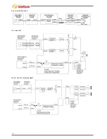
Page 79: ...189 CN6 15 14 415 CN3 15 14 431 FLAT A FLAT B Inverter commands Boost commands ...
Page 80: ...190 By pass relais flow chart Gas valve ELVI Fan M1 and M2 command signal ...
Page 81: ...191 HF command signal AC command signal Torch switch buttons signals ...
Page 88: ...198 HF pulse in TIG AC HF pulse in TIG DC ...
Page 114: ...224 GENESIS 2200 AC DC FP279 ...
Page 115: ...225 GENESIS 1700 AC DC FP216 ...
Page 116: ...226 GENESIS 2200 AC DC FP216 ...
Page 118: ...228 20 CONNETTORI CONNECTORS GENESIS 1700 AC DC FP279 GENESIS 2200 AC DC FP279 ...
Page 119: ...229 GENESIS 1700 AC DC FP216 GENESIS 2200 AC DC FP216 ...
Page 122: ...232 55 08 022 55 08 023 GENESIS 1700 AC DC FP216 GENESIS 2200 AC DC FP216 ...