


217
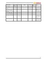
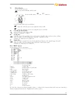
15) ADVANCED SET-UP (cod. 358 menu' Serv)
15.1) List of set up parameters (MMA)
2
(Hot start) Slope-up
Minimum 0.01s, Maximum 2.00s, Default 0.08s
4
(Hot start) Slope-down
Minimum 0.01s, Maximum 2.00s, Default 0.80s
101 (MMA) AC wave form
Allows the selection of the required AC wave form.
Default
102
(MMA) AC frequency
Allows regulation of the polarity inversion frequency in TIG AC welding.
Allows focusing action and better stability of the electric arc to be obtained.
Parameter setting: Hertz (Hz).
Minimum 20Hz, Maximum 200Hz, Default 100Hz
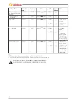
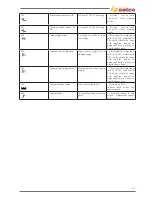
201 No-load
voltage
Minimum 12V, Maximum 80V, Default 80.0V
203 Antisticking
enable
Permits enabling or disabling of the antisticking function.
The antisticking function permits reduction of the welding current to 0A in the event of a short circuit occurring between
the electrode and the piece, protecting the gun, electrode and welder and guaranteeing safety in the condition that has
occurred.
ON Antisticking active
OFF Antisticking not active
0.1÷2.0 The short circuit time before the antisticking function intervenes
Default 0.5s
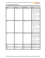
501 Info
Allows the display of a set of information related to the system (Consult the “INFO” screen).
502 Alarm
queue
Allows the intervention of an alarm to be indicated and provides the most important indications for the solution of any
problem encountered.
(Consult the “Alarms screen” section).
704 Offset
calibration
Lets you calibrate the system.
Do not perform calibration in MMA mode.
Short circuit the system’s
and
connectors.
Press the encoder knob to perform calibration.
Repeat the calibration process if you update the software (DSP).
Repeat the calibration process if you change the control card (DSP).
800 Read
filter
Lets you filter current and voltage readings.
Minimum 1, Maximum 5, Default 1
Summary of Contents for Genesis 1700 AC/DC
Page 1: ...Genesis 1700 AC DC Genesis 2200 AC DC MANUALE DI RIPARAZIONE REPAIR MANUAL ...
Page 51: ...161 PFC S POWER COMPONENTS D11 IG1 IG2 D1 D7 CN3 M1 CN4 CN5 CN8 CN7 M2 CN6 ...
Page 52: ...162 PFC STAGE LEDS INDICATIONS PFC s POWER COMPONENTS L2 L1 IG1 IG2 D1 CN6 D7 D11 ...
Page 54: ...164 INVERTER STAGE CN3 M1 CN4 CN5 CN8 CN7 M2 Inverter IMS power module ...
Page 62: ...172 15 Remove pcb T3 PFC s POWER COMPONENTS IG1 IG2 D1 NTC1 Unscrew torque screw at 2 2N mt ...
Page 64: ...174 DIODES AND PFC IGBT ORIENTATION Landmark for assembling ...
Page 67: ...177 12 4 Thermic caps inverter side NTC1 T3 CN11 ...
Page 69: ...179 12 5 Thermic caps secondary side T1 T2 15 14 434 CN3 CN2 ...
Page 74: ...184 15 14 439 15 14 42901 L3 L4 L1 L2 ...
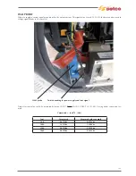
Page 75: ...185 Gas valve flow chart signal Pipe 38 39 ...
Page 79: ...189 CN6 15 14 415 CN3 15 14 431 FLAT A FLAT B Inverter commands Boost commands ...
Page 80: ...190 By pass relais flow chart Gas valve ELVI Fan M1 and M2 command signal ...
Page 81: ...191 HF command signal AC command signal Torch switch buttons signals ...
Page 88: ...198 HF pulse in TIG AC HF pulse in TIG DC ...
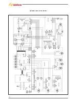
Page 114: ...224 GENESIS 2200 AC DC FP279 ...
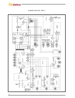
Page 115: ...225 GENESIS 1700 AC DC FP216 ...
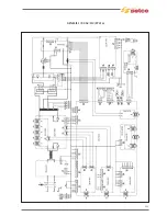
Page 116: ...226 GENESIS 2200 AC DC FP216 ...
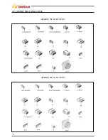
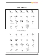
Page 118: ...228 20 CONNETTORI CONNECTORS GENESIS 1700 AC DC FP279 GENESIS 2200 AC DC FP279 ...
Page 119: ...229 GENESIS 1700 AC DC FP216 GENESIS 2200 AC DC FP216 ...
Page 122: ...232 55 08 022 55 08 023 GENESIS 1700 AC DC FP216 GENESIS 2200 AC DC FP216 ...