


204
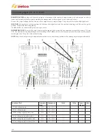
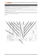
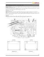
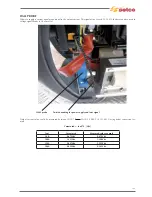
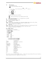
12.14) Bus pcb ref. 15.14.431
BOARD FUNCTION:
the board contains the bus connectors for the rack’s pcb, realizing intercommunication between them and
bringing the various signals through dedicated connectors to external /internal device. Contains a memory circuit for diagnostics and
system configuration.
LOCATION:
located at the base of the rack cards. Connected in a central position at the top, has several connections with various
generator’s units.
DISMANTLING NOTE:
will be useful to remove all connections from CN7 to CN17. Remove rack cards as well. Remove the screws
on pcb’s board.
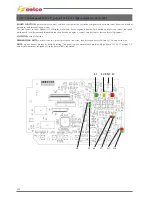
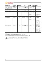
NOTE:
the memory circuit includes a single generator’s information : is therefore necessary, before changing the card ,to contact
the service at [email protected] for testing and management of board to be replaced. Connectors pinning available at par.
“Connectors”.
CN7
CN8
CN9
CN10
CN11
CN12
CN13
CN14
CN15
CN16
CN17
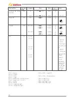
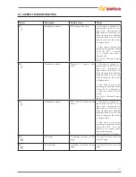
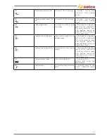
Functional Part
Generator/
Mode
Component
Point Value
Type
of
Measure
Notes
+15Vdc CAN bus voltage
supply
ON
CN8
CN8/1
CN8/2
+15Vdc
Supply voltage
ON
CN9
CN9/3
CN9/4
CN9/6
CN9/4
+15Vdc
+5Vdc
Hall sensor
ON
CN10
CN10/7
CN10/2
0.68@50A
1.37@100A
2.02@150A
2.71@200A
3.38@250A
Stick mode
NTC1
ON
CN11
CN11/1
CN11/7
12kohm
@T=25°C
T1
ON
CN11
CN11/2
CN11/8
0ohm
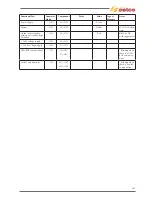
+48Vdc CAN bus volta-
ge supply
ON
CN12
CN12/1
CN12/5
+48Vdc
+24Vdc CAN bus volta-
ge supply
ON
CN13
CN13/5
CN13/8
+24Vdc
Inverter Fan supply M2
ON
CN13
CN13/4
CN13/8
+24Vdc
+15Vdc CAN bus volta-
ge supply
ON
CN16
CN16/1
CN16/3
+15Vdc
Summary of Contents for Genesis 1700 AC/DC
Page 1: ...Genesis 1700 AC DC Genesis 2200 AC DC MANUALE DI RIPARAZIONE REPAIR MANUAL ...
Page 51: ...161 PFC S POWER COMPONENTS D11 IG1 IG2 D1 D7 CN3 M1 CN4 CN5 CN8 CN7 M2 CN6 ...
Page 52: ...162 PFC STAGE LEDS INDICATIONS PFC s POWER COMPONENTS L2 L1 IG1 IG2 D1 CN6 D7 D11 ...
Page 54: ...164 INVERTER STAGE CN3 M1 CN4 CN5 CN8 CN7 M2 Inverter IMS power module ...
Page 62: ...172 15 Remove pcb T3 PFC s POWER COMPONENTS IG1 IG2 D1 NTC1 Unscrew torque screw at 2 2N mt ...
Page 64: ...174 DIODES AND PFC IGBT ORIENTATION Landmark for assembling ...
Page 67: ...177 12 4 Thermic caps inverter side NTC1 T3 CN11 ...
Page 69: ...179 12 5 Thermic caps secondary side T1 T2 15 14 434 CN3 CN2 ...
Page 74: ...184 15 14 439 15 14 42901 L3 L4 L1 L2 ...
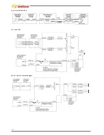
Page 75: ...185 Gas valve flow chart signal Pipe 38 39 ...
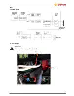
Page 79: ...189 CN6 15 14 415 CN3 15 14 431 FLAT A FLAT B Inverter commands Boost commands ...
Page 80: ...190 By pass relais flow chart Gas valve ELVI Fan M1 and M2 command signal ...
Page 81: ...191 HF command signal AC command signal Torch switch buttons signals ...
Page 88: ...198 HF pulse in TIG AC HF pulse in TIG DC ...
Page 114: ...224 GENESIS 2200 AC DC FP279 ...
Page 115: ...225 GENESIS 1700 AC DC FP216 ...
Page 116: ...226 GENESIS 2200 AC DC FP216 ...
Page 118: ...228 20 CONNETTORI CONNECTORS GENESIS 1700 AC DC FP279 GENESIS 2200 AC DC FP279 ...
Page 119: ...229 GENESIS 1700 AC DC FP216 GENESIS 2200 AC DC FP216 ...
Page 122: ...232 55 08 022 55 08 023 GENESIS 1700 AC DC FP216 GENESIS 2200 AC DC FP216 ...


