Ultraflex Easy Melt Air 1G, Operation Manual
The Ultraflex Easy Melt Air 1G is a cutting-edge device designed for effortless melting. To ensure proper usage, we provide an operation manual that can be easily downloaded for free from manualshive.com. This manual offers comprehensive instructions on how to maximize the performance of this exceptional product.
Share
Download


Reviews:
No comments
Related manuals for Easy Melt Air 1G

HCR3E Series
Brand: HappyJapan Pages: 216

PY Series
Brand: Racing Pages: 13

EC-1 Series
Brand: Toyota Pages: 39

123-1
Brand: Singer Pages: 24

BDP-15D
Brand: Bulldog Security Pages: 7

Citymaster 2000
Brand: HAKO Pages: 186

SFAX-500
Brand: Samyung Pages: 87

W4 Series
Brand: Jack Pages: 58

KM-757
Brand: SunStar Pages: 35

Stairville AF-300
Brand: thomann Pages: 56

FireFighter
Brand: LAI Games Pages: 58

MOBILE MB-1
Brand: Antari Pages: 12

MC 11000 -
Brand: Janome Pages: 13

JUNO E1030
Brand: Janome Pages: 43

LS2-190
Brand: Mitsubishi Pages: 32
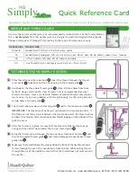
HQ Simply Sixteen
Brand: handi quilter Pages: 2
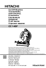
CC 14SF
Brand: Hitachi Koki Pages: 49

LH-4128-7
Brand: JUKI Pages: 89


