


U.2.20
SEL-421/SEL-421-1 Relay
User’s Guide
Date Code 20020501
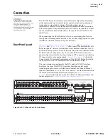
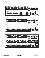
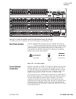
Installation
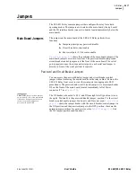
Jumpers
for the locations of these
jumpers. The SEL-421 Relay ships with JMP1, JMP2, and JMP3 OFF (no +5
Vdc on Pin 1).
Changing Serial Port Jumpers
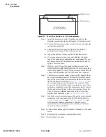
You must remove the main board to access the serial port jumpers. To change
the JMP1, JMP2, and JMP3 jumpers in an SEL-421 Relay, perform the
following steps:
Step 1. Remove the relay from service. Follow your company standard
for removing a relay from service. Disconnect power from the
SEL-421 Relay. Retain the GND connection, if possible, and
ground the equipment to an ESD mat.
Step 2. Remove the front panel from the SEL-421 Relay.
Step 3. Disconnect the power cable, interface board cable(s), and input
board analog cable from the main board (the top board).
Step 4. Remove the screw terminal connectors. Loosen the attachment
screws at each end of the 100-addresses screw terminal
connectors. Pull straight back to remove.
Step 5. Remove rear-panel EIA-232 Ports mating connectors. Unscrew
the keeper screws and disconnect any serial cables connected to
the Port 1, Port 2, and Port 3 rear-panel receptacles.
Step 6. Carefully pull out the drawout assembly containing the main
board.
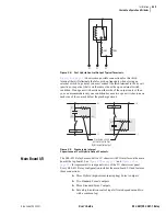
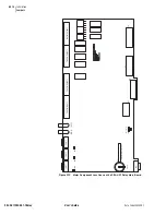
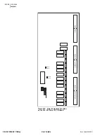
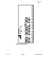
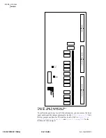
Step 7. Locate the jumper you want to change. Jumpers JMP1, JMP2,
and JMP3 are located at the rear of the main board, directly in
front of Port 1, Port 2, and Port 3, respectively (see
Step 8. Install or remove the jumper as needed. See
for
jumper position descriptions.
Step 9. Reinstall the SEL-421 Relay main board, and reconnect power,
interface board cable(s) and the input board analog cable.
Step 10. Reattach rear-panel connections. Affix the screw terminal
connectors to the appropriate 100-addresses locations on the
rear panel. Reconnect any serial cables that you removed in the
disassembly process to the EIA-232 Ports.
Step 11. Reattach the front panel.
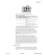
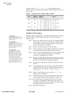
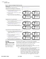
Table 2.4
Main Board Jumpers—JMP1, JMP2, and JMP3
a
a
ON is the jumper shorting both pins of the jumper. Place the jumper over one pin only for OFF.
Jumper
Jumper
Location
Jumper
Position
Function
JMP1
Rear
OFF
Serial Port 1, Pin 1 = not connected
ON
Serial Port 1, Pin 1 = +5 Vdc
JMP2
Rear
OFF
Serial Port 2, Pin 1 = not connected
ON
Serial Port 2, Pin 1 = +5 Vdc
JMP3
Rear
OFF
Serial Port 3, Pin 1 = not connected
ON
Serial Port 3, Pin 1 = +5 Vdc
DANGER:
Contact with
instrument terminals can cause
electrical shock that can result in
injury or death.
!
WARNING:
Have only
qualified personnel service this
equipment. If you are not qualified to
service this equipment, you can
injure yourself or others, or cause
equipment damage.
!
CAUTION:
Equipment
components are sensitive to
electrostatic discharge (ESD).
Undetectable permanent damage
can result if you do not use proper
ESD procedures. Ground yourself,
your work surface, and this
equipment before removing any
cover from this equipment. If your
facility is not equipped to work with
these components, contact SEL
about returning this device and
related SEL equipment for service.
!
Summary of Contents for SEL-421
Page 8: ...This page intentionally left blank ...
Page 30: ...This page intentionally left blank ...
Page 110: ...This page intentionally left blank ...
Page 204: ...This page intentionally left blank ...
Page 284: ...This page intentionally left blank ...


