


U.2.9
Date Code 20020501
User’s Guide
SEL-421/SEL-421-1 Relay
Installation
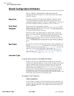
Shared Configuration Attributes
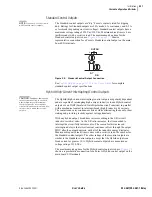
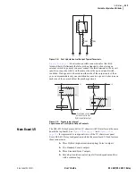
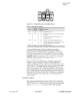
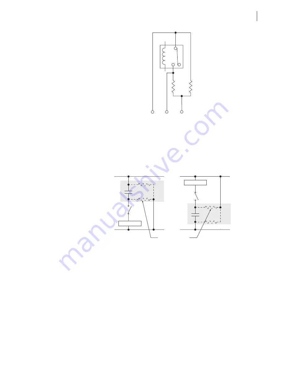
Figure 2.8
Fast Hybrid Control Output Typical Terminals.
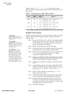
shows some possible connections for this third
terminal that will eliminate the false pick-up transients when closing an
external switch. In general, you must connect the third terminal to the dc rail
(positive or negative) that is on the same side as the open external switch
condition. If an open switch exists on either side of the output contact, then
you can accommodate only one condition because two open switches (one on
each side of the contact) defeat the precharge circuit.
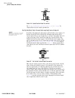
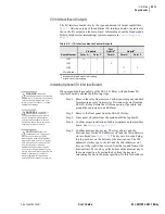
Figure 2.9
Precharging Internal
Capacitance of Fast Hybrid Output Contacts.
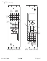
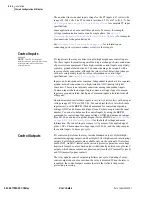
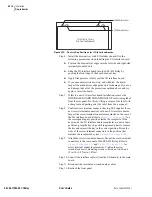
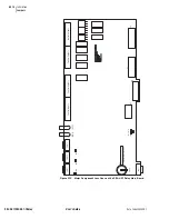
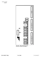
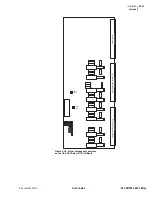
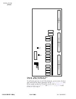
Main Board I/O
The SEL-421 Relay base model is a 3U chassis with I/O interface on the main
board (the top board). See
and
for representative rear-panel views of the 3U chassis rear panel.
Every SEL-421 Relay configuration includes the main board I/O and features
these connections:
➤
Three Hybrid (high-current-interrupting) Form A outputs
➤
Two Standard Form A outputs
➤
Three Standard Form C outputs
➤
Seven high-isolation control inputs (five independent and two
with a common leg)
03
1M
Ω
1M
Ω
02
01
Load
Load
(+)
(+)
(–)
(—)
Precharge circuit
path internal to Fast
Hybrid control output
01
02
02
01
03
03
Summary of Contents for SEL-421
Page 8: ...This page intentionally left blank ...
Page 30: ...This page intentionally left blank ...
Page 110: ...This page intentionally left blank ...
Page 204: ...This page intentionally left blank ...
Page 284: ...This page intentionally left blank ...


