


U.4.59
Date Code 20020501
User’s Guide
SEL-421/SEL-421-1 Relay
Basic Relay Operations
Operating the Relay Inputs and Outputs
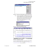
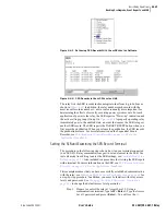
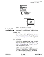
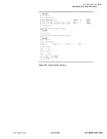
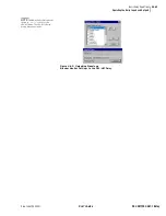
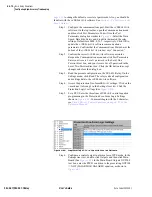
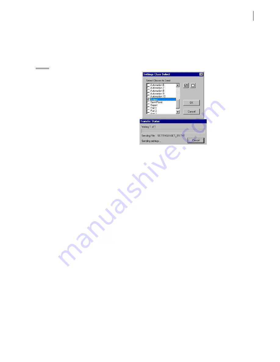
Step 7. Upload the new settings to the SEL-421 Relay. On the File
menu, click Send. The
AC
SEL
ERATOR
software prompts you
for the settings class or instance you want to send to the relay.
Click the check box for Outputs as shown in the first dialog box
of
. Click OK. The
AC
SEL
ERATOR
software
responds with the second dialog box of
. If you see
no error message, the new settings are loaded in the relay.
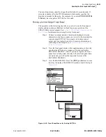
NOTE:
The Relay Editor dialog boxes
shown in
SEL-421 Relay. The SEL-421-1 Relay
dialog boxes are similar.
Figure 4.54
Uploading Output Settings to the SEL-421 Relay.
Control Input
Assignment
The SEL-421 Relay features high-isolation direct connection control inputs
that the relay uses to detect contact closures and signal level changes in an
equipment bay or substation control house. See
for more information on control inputs.
If all of the control inputs share common signal properties of assertion level,
debounce time, and dropout or deassertion level, you can enter these settings
for all inputs. These settings are
GINP
,
GIND
, and
GINDF
for global input
pickup level, global input debounce, and global input dropout (hysteresis)
factor, respectively. See
Global Settings on page R.9.3 in the Reference
for more information. When you enable setting EICIS (Enable
Independent Control Input Settings), you can set separate specific
assert/deassert levels and debounce times for control inputs that are
exceptions to these global control input settings.
Setting a Control Input:
Circuit Breaker Auxiliary Contacts (52A): Terminal
This is a step-by-step procedure to configure a control input that reflects the
state of the circuit breaker auxiliary (52A) NO (normally open) contact. A
common relay input is from circuit breaker auxiliary contacts; the relay
monitors the 52A contacts to detect the closed/open status of the circuit
breaker. Perform the following steps to connect three-pole circuit breaker
auxiliary contacts to the SEL-421 Relay. This example is for a 125 Vdc
system; the open state of the auxiliary contacts is 0 Vdc (circuit breaker open),
and the closed state of the auxiliary contacts is approximately 125 Vdc (circuit
breaker closed). The voltage drop in the connecting wires from the auxiliary
contacts through the station battery to the relay gives a slightly lower voltage
than the station battery at the relay control input terminals. The default value
for GINP (Global Control Input Pickup Level) at 85 Vdc is sufficient.
Summary of Contents for SEL-421
Page 8: ...This page intentionally left blank ...
Page 30: ...This page intentionally left blank ...
Page 110: ...This page intentionally left blank ...
Page 204: ...This page intentionally left blank ...
Page 284: ...This page intentionally left blank ...


