


U.6.18
SEL-421/SEL-421-1 Relay
User’s Guide
Date Code 20020501
Testing and Troubleshooting
Test Methods
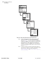
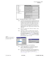
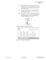
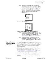
NOTE:
The Relay Editor dialog boxes
shown in
are for the
SEL-421 Relay. The SEL-421-1 Relay
dialog boxes are similar.
Figure 6.10
Uploading Front-Panel Settings to the SEL-421 Relay.
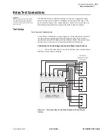
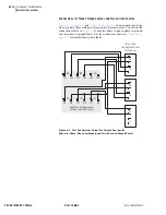
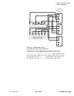
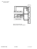
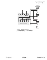
Step 5. Connect a test source to the relay. Set the current output of a
test source to zero output level. Connect a single-phase current
output of the test source to the IAW analog input (see
Secondary Circuits on page U.2.5
).
Step 6. View the target status change. Increase the current source to
produce a current magnitude greater than 10.00 A secondary in
the relay. Observe the LED next to the RELAY TEST MODE
pushbutton (PB4) on the SEL-421 Relay front panel. You will
see the LED light when the input current exceeds the 50P1P
setting threshold.
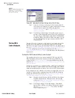
Testing With
Control Outputs
You can set the relay to operate a control output to test a single element. Set
the SEL
OGIC
control equation for a particular output (OUT101 through
OUT108, for example) to respond to the Relay Word bit for the element under
test. See
Operating the Relay Inputs and Outputs on page U.4.52 in the User’s
for configuring control inputs and control outputs. The
Relay Word Bits in the Reference Manual
lists the names of the relay element
logic outputs.
Testing the 50P1 Element With a Control Output
This procedure shows how to set control output OUT105 to test the 50P1
Phase Instantaneous Overcurrent element. Use the factory defaults for the
pickup level (see
). For more information on the 50P
elements, see
Instantaneous Line Overcurrent Elements on page R.1.62 in the
For this test, you must have a computer with the
AC
SEL
ERATOR
software for
the SEL-421 Relay, a variable current source for relay testing, and a control
output closure indicating device such as a test set or a VOM (volt ohmmeter).
In this example, use the
AC
SEL
ERATOR
software to configure the relay. You
must have a computer that is communicating with the SEL-421 Relay and
running the
AC
SEL
ERATOR
software; see
Making Settings Changes: Initial
Global Settings on page U.4.19 in the User’s Guide
.
Step 1. Prepare to control the relay with the
AC
SEL
ERATOR
software.
Establish communication, check passwords, and read relay
settings; see
Making Settings Changes: Initial Global Settings
on page U.4.19 in the User’s Guide
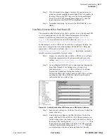
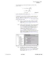
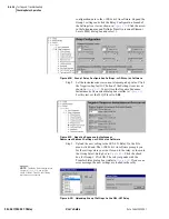
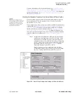
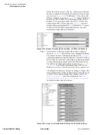
Step 2. View Output settings. Click on the Outputs > Main Board
branch of the
AC
SEL
ERATOR
software Settings tree structure
shown in
. You will see the Main
Board Outputs dialog box.
Summary of Contents for SEL-421
Page 8: ...This page intentionally left blank ...
Page 30: ...This page intentionally left blank ...
Page 110: ...This page intentionally left blank ...
Page 204: ...This page intentionally left blank ...
Page 284: ...This page intentionally left blank ...


