


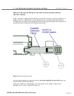


Page 9
STAT
IM 2000/2000S
Service Guide
96-106775 Rev 5.0
1. Identifying STAT
IM 5000 Units
STAT
IM
5000/5000S/5000 G4 Service Guide
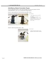
Identifying Controller Board Types
There are three different types of controller boards that may be encountered in STAT
IM 5000/
5000S/5000 G4 type units (See ‘PCB revision’ above). They can be identified as below (Figure 3):
Figure 3
Revision 2.x/5.x type board (1995 – 2004):
Revision 6.x type board (2004 - 2007):
Revision 7.x type board (2007 to present):
Typical features:
•
Revision number bottom right hand
side.
•
Rectangular microprocessor plus
EPROM
•
‘W1’ jumper for calibration
•
Blue ‘pressure interface/printer’
connector
Typical features:
•
Revision number bottom right hand
side.
•
Square microprocessor plus EPROM
•
‘W1’ jumper for calibration
•
Blue ‘pressure interface/printer’
connector
Typical features:
•
Up to revision 7.30, the revision
number is on the top right hand side
(printed vertically)
•
From revision 7.4 onwards, the
revision number is on the bottom left
hand side (printed horizontally) under
the connector J1
•
Square microprocessor plus EPROM
•
NO ‘W1’ jumper for calibration
•
NO Blue ‘pressure interface/printer’
connector
•
All components integrated on single
board
•
Surface mount type component.
•
‘Push in’ yellow thermocouple
connectors.


