


Page 188
STAT
IM 2000/2000S
Service Guide
96-106775 Rev 5.0
8. Water Pumps, Reservoir, and Compressor
STAT
IM
5000/5000S/5000 G4 Service Guide
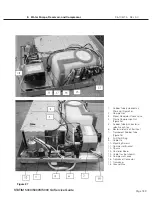
With the additional bacteria-retentive filter:
7B. Connect the rubber tube (5) which extends from the top of the compressor (2) to the input
side of the bacteria-retentive filter (6). Secure the tube at the compressor end with the plastic
compression nut (4).
8. Test the compressor by activating the compressor using a control box or key pad, as appropriate.
9. A dielectric strength test (Hi-Pot) AND a protective bonding impedance test (ground continuity)
must be performed on the STAT
im
when the work is completed and after the cover has been
returned to the unit.
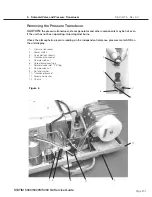
Removing and Reinstalling the Thomas Compressor
Removing the Thomas Compressor
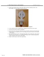
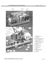
To remove the Thomas (or SciCan) Compressor, follow these steps: (see Figure 27):
1. Turn the power switch OFF, and unplug the unit.
2. Disconnect the leads from controller board (13) terminal block positions J1-9 LINE and J1-10
NEUTRAL, and carefully cut the cable ties (14) securing the compressor leads (15).
3. Cut the cable tie on the Teflon tubing connected to the top of the compressor (2) and leading to
the input side of the bacteria-retentive filter.
4. Unscrew the four screws (10) attaching the compressor bracket to the chassis.
5. If there is a pressure transducer (17) attached to the bracket, turn the compressor and bracket
assembly over to loosen the fastening nut and remove the pressure transducer.
6. Remove the four screws on the underside of the bracket to separate the compressor from the
bracket.
7. Remove the ground wire (18) from the compressor.
Replacing the Thomas Compressor
To replace the Thomas (or SciCan) Compressor, follow these steps (see Figure 3 and 4):
1. Connect the ground wire (18) to the compressor body.
2. Reconnect the pressure transducer connector (16) to the transducer (17), if present.
3. Position the compressor / bracket assembly (11) in the chassis (12). Route the compressor
leads (15) with the bundle of wires leading to the controller board (13). Connect the black lead to
controller board terminal block position J1 - 9 LINE and the white wire to terminal block position
J1-10 NEUTRAL.
4. Bundle the wires together and secure them using nylon cable ties (14) every 2 - 3 inches.
5. Reinstall the four bracket screws (10) retained during disassembly. Do not crush wires or tubes.
6. Connect the Teflon tube (5), which extends from the top of the compressor (2) to the input side of
the bacteria-retentive filter (6). Secure the tube at the compressor end with the plastic cable tie (g).
7. Test the compressor by activating the compressor with a control box or key pad, as appropriate.
8. A dielectric strength test (Hi-Pot) AND a protective bonding impedance test (ground continuity)
must be performed on the STAT
im
when the work is completed and after the cover has been
returned to the unit.


