


Page 245
STAT
IM 2000/2000S
Service Guide
96-106775 Rev 5.0
12. Printer and Data Logger
STAT
IM
5000/5000S/5000 G4 Service Guide
1
2
3
4
5
18
19
20
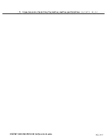
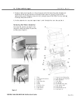
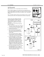
1. Cover
2. Printer module assembly
3. Hinge pin
4. Snap mechanism
5. Spring
6. Screws
7. Printer housing
8. Printer board
9. Paper roll arm
10. Printer door
11. Paper roll arm retaining clips
12. Printer board mounting holes
13. Mounting bosses
14. Printer body
15. Locating ribs
16. Print head flexible cable
17. Printer ribbon cable
18. Power button
19. Paper advance button
20. Paper feed slot
Figure 2
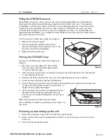
2. To adjust and test print quality, turn the unit power switch ON. Open the printer module and
enable the printer by pressing the printer power button (item 18, Figure 2). Start and then
quickly stop a cycle. Doing so causes an error message to be printed. While the error message
is printing, adjust the pot (R21).
3. If further adjustment is required, repeat steps 1 and 2. Reinstall the cover. See section 6
Removing the Printer Assembly
To remove the printer assembly (1) from
the printer module assembly (2), proceed
as follows (see Figure 2):


