


Page 177
STAT
IM 2000/2000S
Service Guide
96-106775 Rev 5.0
8. Water Pumps, Reservoir, and Compressor
STAT
IM
5000/5000S/5000 G4 Service Guide
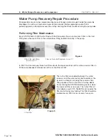
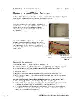
6. Place the unit back on its feet and carefully remove the reservoir from the chassis. BE CAREFUL
NOT TO DAMAGE THERMOCOUPLE LEADS.
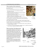
Reinstalling the reservoir
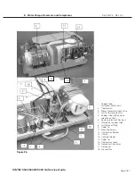
To reinstall the reservoir, follow these steps (see Figure 19):
1. Carefully place and secure the reservoir (1) in the chassis taking care not to damage the wiring.
2. Tilt the unit on its side so that the reservoir and PCB are at the top of the unit. Locate and install
the three retained nylon cap nuts with washers (9)on the bottom of the chassis securing the
reservoir. Do not pinch or obstruct the drain tube.
3. Place the unit back on its feet.
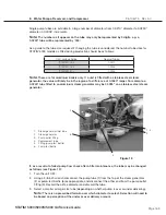
4. Reconnect the reservoir supply tube (7) to the “T”-fitting (8). Secure the tube using a cable tie (4).
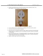
5. Fill the reservoir with steam-process distilled water.
TIP: Touch the leads of the water quality sensor assembly to an earthed point to discharge
any static electric charge which may have built up on the reservoir during shipping. This
reduces the chance of damaging the controller board with ESD.
6. Connect the water quality sensor leads (4) to controller board (5) terminal positions labeled
PROBE J4-3 and J4-4.
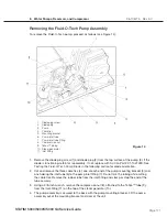
7. Reinstall the compressor / bracket assembly (3). See, Reinstalling the Compressor.
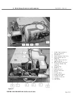
8. Bundle the reservoir sensor leads, the microswitch leads and the thermocouple leads together
and secure them using cable ties every 2-3 inches. Secure the bundle to the top of the armature
using the clamps provided.
9. Reinstall the cover.
10. A dielectric strength test (Hi-Pot) AND a protective bonding impedance test (ground continuity)
must be performed on the STATIM when the work is completed and after the cover has been
returned to the unit.


