


Page 158
STAT
IM 2000/2000S
Service Guide
96-106775 Rev 5.0
7. Electrical and Electronic Components
Receptacle / line Filter
It is difficult to determine whether a line filter has failed or not. If the unit blows mains fuses
in the service panel, there may be a short in the line filter. Disconnect all leads from the mains
input and output and test for short circuits.
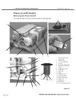
Removing the Receptacle / line Filter
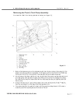
To remove a line filter (3), proceed as follows, (See Figure 21):
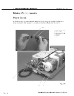
1. Turn the power switch (2) OFF, and unplug the power cord (1) from the wall outlet.
2. Remove the power cord from the unit. See, Removing a Detachable Power Cord.
3. Remove the four screws (5) holding the compressor assembly (6) to the chassis (7) and rest
the compressor to one side. Do not bend the thermocouple leads (8). See, Compressor.
4. Disconnect the white wire (4a) from receptacle line filter position N, the black wire (4b) from
line filter position P and the green wire (4c) from line filter position. If access to the back of the
line filter is impeded, disconnect the pump inlet tube.
5. Remove the screws (18) holding the filter to the chassis (7) and remove the filter.
Replacing/refitting the Receptacle / line Filter
To replace/refit a line filter (4), proceed as follows, (See Figure 21):
1. Insert the line filter in the opening in the chassis (7). The P and N fast-on spade terminals
should face up, and the ground terminal should face down.
2. Insert and tighten the screws (18) holding the line filter, using Loctite in the threaded holes in
the chassis.
3. Connect the white wire (4a) from the power switch to line filter position N and the black wire
(4b) from the power switch to line filter position P.
4. Connect the green wire (4c) from the ground post to line filter position.
5. If the pump inlet tube was moved, reinstall the tube.
6. Reinstall the compressor assembly (6) using the four screws (5) retained from disassembly.
Do not bend the thermocouple leads (7). See, Compressor.
7. A dielectric strength test (Hi-Pot) and a protective bonding impedance test (ground continuity)
should be performed on the STAT
IM unit at this stage.
NOTE:
These tests must be performed on the STAT
im
again once the work is completed and
the cover has been returned to the unit.
8. Plug the power cord (1) into the line filter and the wall receptacle and turn the power switch (2)
ON. Observe the LCD and indicator lights to determine that power is present.
STAT
IM
5000/5000S/5000 G4 Service Guide


