


Page 197
STAT
IM 2000/2000S
Service Guide
96-106775 Rev 5.0
9. Solenoid Valve and Pressure Transducer
STAT
IM
5000/5000S/5000 G4 Service Guide
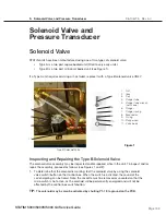
7. Bundle the wires together and secure them using cable ties every 2 to 3 inches.
8. Test the solenoid by activating the solenoid switch on the Control box. Note: the cassette
must be removed or unseated so that the microswitch is not active as the solenoid will be
permanently energized and will not be affected by the control box switch/button.
9. A dielectric strength test (Hi-Pot) and a protective bonding impedance test (ground continuity)
MUST be performed on the unit.
NOTE:
These tests must be performed on the STAT
im
again once the work is completed and
the cover has been returned to the unit.
10. Run a sterilization cycle and observe all fittings and tubes for leaks. Check LCD read-outs for
messages indicating cycle status.
Pressure Transducer
Note:
only ‘S’ type (eu) STAT
IM
models have pressure transducers.
STAT
im
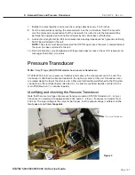
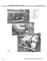
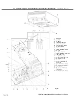
5000S units use a pressure transducer to measure the steam pressure in the unit. The
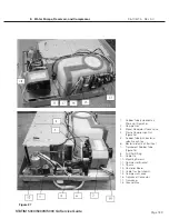
transducer is attached to a bracket located in the right rear corner of the unit. Transducer wires
are routed along the top of the armature to a Pressure Interface Board attached to the P2 printer
connector on the controller board, (Revision 2.x, 5.x and 6.x controller boards), or direct to the
main PCB (Revision 7.x controller boards).
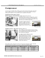
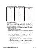
Identifying and checking the Pressure Transducer
Note that there are two types of pressure transducer used on STAT
im
S models, a 0 - 60 p.s.i.
transducer on models up to approximately 2004 and a 0 - 68 p.s.i. transducer on models from
2004 on. The input voltage is the same for both types, but the output voltage is different so
the
two types are not interchangeable
.
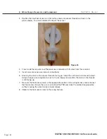
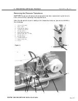
Pressure transducer
Figure 4


