


Page 235
STAT
IM 2000/2000S
Service Guide
96-106775 Rev 5.0
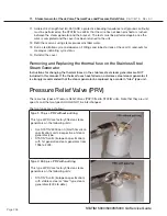
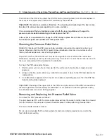
11. Steam Generator, Check Valve, Thermal Fuse and Pressure Relief Valve
STAT
IM
5000/5000S/5000 G4 Service Guide
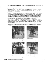
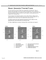
Replacing the Thermal Fuse on the Aluminium Steam Generator
(for all models)
Determine which configuration is being serviced and use the appropriate parts to service the unit.
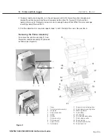
To replace the thermal fuse proceed as follows (refer to Figure 9):
1. Connect the terminal of the appropriate thermal fuse (5 for type A - single) or (8 for type B/C -
double) to the lower power terminal on the steam generator (1 for type A/B) or (10 for type C).
2.
a. For Type A configuration, replace the steam generator bracket (2) with a modified steam
generator bracket (9). Route the wire from the fuse assembly (5) between the standoffs
(7) and the standoffs on the modified steam generator bracket. The fuse must be placed
exactly between the standoffs. Attach the steam generator bracket to the steam generator
(1) using the small screw (4). Do not pinch or crush the wire between components. Ensure
that the screw is tightened securely.
b. For Type B configuration, route the wire from the fuse assembly (8) between the standoffs
(7) on the bottom of the steam generator (1) and the standoffs on the modified steam
generator bracket (9). The fuse must be placed exactly between the standoffs. Attach the
steam generator bracket to the steam generator (1) using the small screw (4). Do not pinch
or crush the wire between components. Ensure that the screw is tightened securely.
c. For Type C configuration, route the wire from the fuse assembly (8) between the two sets
of standoffs (7) on the bottom of the modified steam generator (10).
The fuse must be placed exactly between the standoffs. Attach the steam generator
bracket (2) to the steam generator using the small screw (4). Do not pinch or crush the wire
between components. Ensure that the screw is tightened securely.
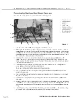
NOTE: For the remainder of the procedure, refer to Figure 11 and proceed as follows.
3. Carefully return and attach the steam generator assembly to the chassis using two screws
(14). Start the screws into the tapped hole but do not tighten the screws. Be careful not to
stress the thermocouple leads. (Min. bend radius - 3/16 inch / 5 mm).
4. Connect the compression nut (12) holding the steam generator outlet tube (10) to the steam
generator outlet fitting (13) and the compression nut (9) holding the steam generator outlet
tube (10) to the probe bracket inlet fitting (11). Tighten finger tight.
5. Connect the compression nut (7) holding the Teflon™ pump tube (8) to the top of the steam
generator. Tighten finger tight, then continue to tighten the nut using a 3/8-inch wrench. Do
not overtighten.
6. Tighten the two screws (14) that attach the steam generator assembly to the chassis.
7. Using a wrench, tighten the compression nut holding the steam generator outlet tube to the
steam generator outlet fitting and also the compression nut holding the steam generator outlet
tube to the probe bracket fitting.
8. Route the black wire (4) from the fuse assembly and connect the wire to Controller Board
connector J1-3. Connect the white wire (12) to the steam generator electrical terminal (19).
9. Bundle the loose wires together in the wiring harness and secure using nylon cable ties every
2-3 inches.
10. Reinstall the compressor tube (6) onto the check valve inlet (3) and secure the tube to the
valve with a high temperature rated cable tie (1).


