


Page 179
STAT
IM 2000/2000S
Service Guide
96-106775 Rev 5.0
8. Water Pumps, Reservoir, and Compressor
STAT
IM
5000/5000S/5000 G4 Service Guide
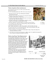
Troubleshooting reservoirs with water quality
sensor only
Diagnosing conductivity sensor problems
Before starting diagnostic procedures check that:
14. The reservoir is free of any debris and the conductivity sensor is clean.
15. The reservoir is filled with good quality steam distilled process water so that the conductivity
sensor is completely submerged. If in doubt about water quality, drain the reservoir and refill
with steam-process distilled water containing less than 5 ppm total dissolved solids or having
conductivity of less than 10 μS/cm.
16. The leads of the conductivity sensor are securely connected to controller board. Nothing is
connected to controller board terminal positions labeled ‘FLOAT’.
17. The controller board is clean and dry (both sides). Pay particular attention to the terminal block
where the sensor is connected and any components on the upper right hand portion of the
board.
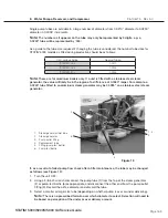
18. For rev 2.x, 5.x and 6.x controller boards, measure the negative voltage across test connector
header positions P1-1 and P1-3. If the voltage reading is not within -8.4V to -9.7V, replace the
controller board.
Checking the conductivity sensor
To check the conductivity sensor, proceed as follows:
1. Power the unit OFF and disconnect the sensor leads from controller board connector positions
J4-3 and J4-4.
2. Power the unit ON and start an Unwrapped cycle.
3. If a “REFILL RESERVOIR, EMPTY WASTE BOTTLE” message appears on the LCD, proceed
to step 4. If the cycle starts when the sensor leads are disconnected, the controller board is at
fault and should be replaced.
4. Short circuit (bridge) controller board connector positions J4-3 and J4-4 together and start a
cycle. If the unit displays a “WATER QUALITY NOT ACCEPTABLE” message, proceed to step
5. If no message is displayed then the controller board is at fault and should be replaced.
5. Remove the short from J4-3 and J4-4 and short controller board connector positions J4-5
and J4-6 together. If the unit displays a “SELECT A CYCLE” message, it is unlikely that the
controller board is damaged.
6. If problems persist, leave the unit powered ON to allow internal components to warm up for a
period of time (some failures are temperature dependent). Then start any sterilization cycle and
repeat steps 1 through 6.
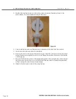
7. To test the conductivity sensor, short the sensor posts in the reservoir using a long handle
screwdriver. The measured resistance across the unconnected sensor leads should be less
than 1.0 ohm. If the reading is other than that the sensor is likely damaged. Replace the
sensor.


