


Page 174
STAT
IM 2000/2000S
Service Guide
96-106775 Rev 5.0
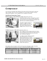
8. Water Pumps, Reservoir, and Compressor
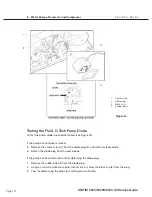
Removing the SciCan or ulka Pump Assembly
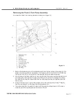
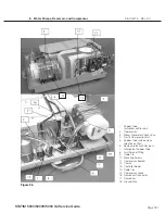
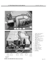
To remove the pump assembly follow these steps (see Figure 16):
1. Remove the four screws with washers securing the compressor / bracket assembly. See,
Compressor.
2. If the pressure transducer is present, disconnect the transducer connector. See, STAT
im
Pressure Transducer.
3. Remove the compression nut holding the compressor output tube to the compressor and
disconnect the tube. Rest the compressor bracket assembly to one side to access the pump.
4. Clip and remove the cable tie (1) holding the inlet tube (2) to the pump inlet fitting (3). Do not
nick the tubing while cutting the cable tie. Remove the rubber tube from the inlet fitting and
clamp or stop the end of the tube securely.
5. Using a 3/8-inch wrench, remove the compression nut (4) attached to the Teflon™ tube (5), from
the inlet fitting (6) on the top of the steam generator (7).
6. Disconnect the fast-on terminal connectors (8) from the pump. Observe the position of each
terminal before removal.
7. The pump assembly is secured to the chassis by rubber brackets (9) and four shoulder screws
(10). Remove the four shoulder screws and retain for re-assembly. Remove the pump assembly
from the chassis.
Figure 16
(Ulka Pump shown)
10
8
9
5
10
1
2, 3
7
6
4
1. Cable tie
2. Inlet tube
3. Pump inlet fitting
4. Compression nut
5. Teflon tube
6. Inlet fitting
7. Steam generator
8. Terminal connectors
9. Rubber brackets
10. Screws
STAT
IM
5000/5000S/5000 G4 Service Guide


