


Page 141
STAT
IM 2000/2000S
Service Guide
96-106775 Rev 5.0
7. Electrical and Electronic Components
STAT
IM
5000/5000S/5000 G4 Service Guide
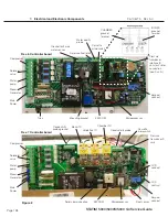
All Boards
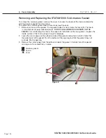
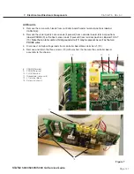
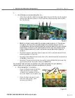
2. Remove the microswitch leads from controller board header terminal positions labeled
CASSIN (8).
3. Remove the water quality sensor leads (if present) from controller board terminal positions
labeled PROBE (9) or the float sensor leads (if present) from terminal positions labeled FLOAT
(10).
Note that on later units a third, ground wire (11) may be present as well as the two
PRoBe wires.
4. Disconnect all high voltage leads from controller board block terminal J1 (12).
5. Remove and retain the three screws (13) with washers that secure the controller board
assembly to the chassis.
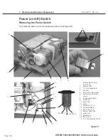
Figure 7
11
13
8
9
10
12
8. CASSIN Terminal
9. PROBE Terminal
10. FLOAT terminal
11. Groundwire (some units)
12. J1 terminal block
13. Screws to chassis


