47
TSA-SA70 OWNER’S MANUAL
Setting the Bearing Tension
For installations WITH OR WITHOUT the extension wing.
Requires:
5mm Hex Wrench
10mm
Wrench
3/4”
Socket
1
2
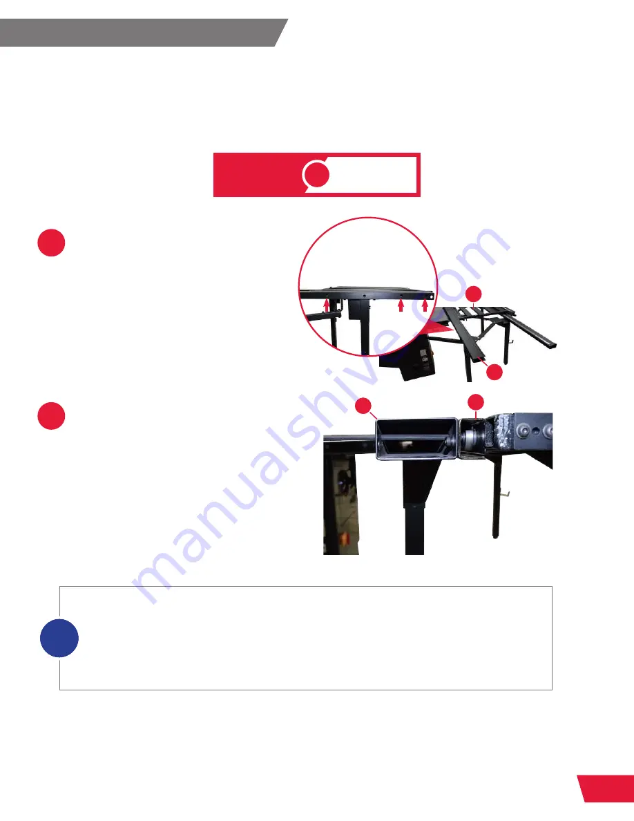
Slide the sliding table
(M)
toward
the rear of the guide tubes, until the
access holes in the bearing guide
channel and inner guide tube
(A)
line
up with the three socket head cap
screws in the sliding table.
Use a 5mm hex wrench to slightly
loosen the three socket head cap
screws securing the three adjustable
ball bearings on the side of the sliding
table
(M)
closest to the table saw,
using the access holes in the inner
guide tube and guide bearing
channel
(A)
.
There are five bearings on the side of the sliding table closest to the saw table. The bearing
closest to the front of the saw is not adjustable. The second bearing is adjustable to prevent
vertical movement of the front of the sliding table. The third bearing is adjustable to prevent the
sliding table from “jumping” at the front and back of the guide tubes. The fourth bearing is not
adjustable. The fifth, and furthest back, bearing is adjustable to prevent vertical movement of the
rear of the sliding table. (See the exploded view on page 94 for reference). The two non-adjustable
bearings are each partially covered by a guide channel scraper.
i
M
A
M
A
WITH
WITHOUT
EXTENSION WING
OR


