RFX144V24-S23 and RFX96V24-S23 Modem Designer’s Guide
3-22
1070
3.2.5 DTMF
Receiver
Mode Selection and Description
Configuration code 21h enables the DTMF receiver to operate concurrently with the FSK receiver and the three tone
detectors. Configuration codes 90h or 98h and 92h or 94h also enable the DTMF receiver to operate concurrently with the
three tone detectors in the Voice Codec and Audio Codec modes. DTMF receiver operates in the Audio modes,
configuration codes 82h and 86h, during audio playback.
The encoded DTMF receiver output is written into the four least significant bits of register 1C.
The modem sets the DTMF Signal Detected status bit, DTMFD (1C:4), to a 1 whenever a DTMF signal is successfully
detected. The host must reset DTMFD after reading the register, otherwise, two or more successive detections of the same
symbol may go unnoticed.
Other DTMF Reception Status Bits
Other status bits have been included in register 1C to facilitate host DTMF detection, primarily when used with the
programmable interrupt. The Early Detection bit, EDET (1C:7), may set to a 1 approximately 20 ms after signal energy is
detected. Setting this bit informs the host that the received signal appears to be a DTMF signal, but the modem has not yet
completed its processing.
The Dual Tone Detected bit, DTDET (1C:6), may set to a 1 approximately 11 ms following EDET setting. DTDET is set when
the received signal satisfies all DTMF criteria except on-time, off-time, and cycle-time. At this time the encoded DTMF
receiver output is made available to the host in the DTMF Output Word (1C:0-3). If DTDET is not set to a 1, then the
received signal has failed one or more criteria, and consequently the modem resets EDET and resumes its search.
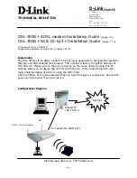
After the on-time criteria is satisfied, the modem sets the On-Time Satisfied bit, OTS (1C:5), to a 1. If the on-time is not
satisfied, the modem resets bits EDET and DTDET and resumes its search. As soon as both the off-time and cycle-time are
satisfied, DTMFD is set to a 1. If these times are not satisfied, then EDET, DTDET, and OTS are reset and the receiver
resumes its search. Also following DTMFD setting, EDET, DTDET, and OTS are reset. The relationship between these
status bits for a valid DTMF signal is illustrated in Figure 3-3.
If, after DTDET is set to a 1, the host resets DTDET before OTS sets to a 1, then the DTMF receiver is reset to its initial
state except for the programmable DTMF parameters which retain their present values (see Section 4.2).
If, after OTS is set to a 1, the host resets OTS before DTMFD sets to a 1, then the DTMF receiver is reset to its initial state
except for the programmable DTMF parameters which retain their present values (see Section 4.2).
See Table 13-1 for DTMF receiver performance characteristics.
Note: The DTMF copy bits (EDETC, DTDETC, OTSC, and DTMFDC in register 17) copy the corresponding actual DTMF
status bits (EDET, DTDET, OTS, and DTMFD, respectively, in register 1C). The copy bits are located in the same register as
the status bits for tone detection, ring detection, and Voice Mode status bits to facilitate programmable interrupt service.
Clearing the DTMFD status bit will automatically clear the corresponding DTMFDC copy bit within one sample time.
~11 ms
~20 ms
FED
1070F3-3 DTMF Timing
DTMFD
(PROGRAMMABLE)
OTS
(PROGRAMMABLE)
DTDET
EDET
Figure 3-3. DTMF Receiver Status Bit Timing
Summary of Contents for RFX144V24-S23
Page 197: ......