RFX144V24-S23 and RFX96V24-S23 Modem Designer’s Guide
1070
6-1
6. TONE DETECTOR FILTER TUNING
This section describes a method of tuning the filters in the modem for tone detection. This method is the same as for other
MONOFAX modems.
6.1 PROGRAMMABLE TONE DETECTORS
The modem includes three independently programmable tone detectors (F1, F2, and F3). In speakerphone configuration,
only tone detector 1 is operational. Tone detectors are not provided in V.23 (CONF = 24h, -23 option). Upon power-up, the
tone detectors are centered at 2100 Hz (F1), 1100 Hz (F2), and 462 Hz (F3); the sample rate is 9600 Hz only.
In each of the three detectors, two second-order biquadratic filters can be programmed for a variety of frequency responses.
The modem sets interface memory bits FR1, FR2, and FR3 to a 1 when tone detectors 1, 2, and 3 detect energy above their
respective threshold. This application note presents a method of tuning these detectors to any frequency in the 400 Hz -
3000 Hz band.
By setting bit 12TH to a 1 in the interface memory, the three tone detectors are cascaded to form a programmable 12th-
order filter. In this case the modem sets only the FR3 bit to a 1 when energy is above the threshold.
6.1.1 Computation of Tone Detector Coefficients
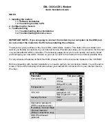
Each tone detector consists of two cascaded second-order filters, an energy averaging filter, and a threshold comparator. A
diagram of a tone detector is shown in Figure 6-1.
INPUT
BIQUADRATIC FILTER 1
BIQUADRATIC FILTER 2
h1(t)
h3(t)
h2(t)
2
α
’
0
α
’
1
α
’
2
α
0
α
”
α
1
α
2
2
ABS
Z
-1
Z
-1
Z
-1
Z
-1
Z
-1
Z
-1
Z
-1
β
1
β
2
β
'
1
β
'
2
OUTPUT
FR1, FR2, FR3
THRESHOLD
COMPARATOR
ENERGY AVERAGING FILTER
β
”
1070F6-1
1 = TONE
0 = NO TONE
Σ
Σ
Σ
Figure 6-1. Modem Tone Detection Diagram
Summary of Contents for RFX144V24-S23
Page 197: ......