background image

RIGOL 

© Copyright 

RIGOL 

Technologies, Inc. 2007                                                                                 

2-49


User’s Guide for DG1000 Series


To Store and Recall 

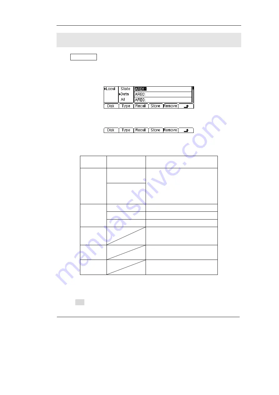
Press Store/Recall Button, and the operation menu will appear at the bottom of the 
screen. You can save or read the State or Data Documentation inside the Generator 
or build and delete documentation in the U Disk. File names can either be Chinese or 
English. 


Figure 2-64    Save and Read Interface 


Figure 2-65    Operation Menu 

Table 2-24    Save and Read Menu 

Function  

Menu 

Settings Explanation


Local 

Disk 

U Disk 

(When U Disk is 
connected ) 

Choose display route for the 

system information   

State 

Setting of the Generator 

Data 

Arbitrary waveform file 

Type 

All 

All types of documentation 

Recall  

Recall the waveform or Setting 

information in the specific 
position in the memory. 

Store 


Save the waveform to the 

appointed place. 

Remove  

Remove any waveform that 
has been stored in the memory 


About the Disk 

Use the Disk button to choose Local or U Disk (When U Disk is connected). 

Summary of Contents for DG1000 Series

Page 1: ...User s Guide RIGOL Publication number DG1 070518 May 2007 DG1000 Series Function Arbitrary Waveform Generator Copyright RIGOL Technologies Inc 2007 All Rights Reserved...

Page 2: ......

Page 3: ...protected by patent law in and outside of P R China z Information in this publication replaces all the corresponding materials published previously z RIGOL Technologies Inc reserves the right to modif...

Page 4: ...unded through the protective terra conductor of the power cord To avoid electric shock the grounding conductor must be connected to the earth ground Make sure that the instrument is properly grounded...

Page 5: ...h the exposed connections or components when the power is turn on Do not operate with suspected failures If you suspect there is damage with this product have it inspected by qualified service personn...

Page 6: ...could result in damage to this product or other property Terms on the Product These terms may appear on the product DANGER indicates an injury or hazard that may be immediately happen WARNING indicat...

Page 7: ...aph interface built in instructions and help system have greatly simplified the operation process thus users do not have to spend a great deal of time learning and familiarizing the operation of the g...

Page 8: ...ternal 10 MHz Reference output z Support USB storage device Could store and read waveform configure parameters or the edited arbitrary waveform with USB devices System Updating could also be performed...

Page 9: ...ng Your Generator 2 1 The Menu Graph Mode 2 2 To Set Sine Signals 2 3 To Set Square Signals 2 7 To Set Ramp Signals 2 10 To Set Pulse Signals 2 12 To Set Noise Signals 2 14 To Set Arbitrary Signals 2...

Page 10: ...o Generate an FSK Waveform 3 11 Example 10 To generate a Linear Sweep Waveform 3 13 Example 11 To generate a Burst Waveform 3 15 Example 12 To measure the frequency 3 17 Chapter 4 Prompt messages trou...

Page 11: ...arted This chapter covers the following topics General Inspection To Adjust the Handle The Front rear Panel of DG1000 Series The User Interface of DG1000 Series To Set a Waveform To Set Modulation Swe...

Page 12: ...upplied with the instrument are listed in chapter 6 Appendix B DG1000 Series Accessories If the contents are incomplete or damaged please contract the local selling representative of RIGOL 3 Inspect t...

Page 13: ...handle position of DG1000 Function Arbitrary Waveform Generator please grip the handle by the sides and pull it outward Then make the handle rotate to the desired position The operating methods are s...

Page 14: ...ons of the Front Rear Panel The Front Panel at a Glance DG1000 Series Function Arbitrary Waveform Generator has clear and simple front panel See Figure 1 3 and Figure 1 4 The Front Panel has a knob fu...

Page 15: ...L Copyright RIGOL Technologies Inc 2007 User s Guide for DG1000 Series 1 5 Figure 1 4 Front Panel Operation Instruction for DG1000 Series The Rear Panel at a Glance Figure 1 5 Rear Panel for DG1000 Se...

Page 16: ...RIGOL Copyright RIGOL Technologies Inc 2007 User s Guide for DG1000 Series 1 6 Figure 1 6 Rear Panel Operation Instruction for DG1000 Series...

Page 17: ...n menu will appear at the bottom of the screen when you press any menu button These two display modes can be switched to each other by pressing the A button Figure 1 7 The menu Display Mode Interface...

Page 18: ...erate Sine signal with frequency from 1 Hz to 20MHz By setting Frequency Period Amplitude High Level Offset Low level sine signal with different parameters can be generated Figure 1 10 Sine Signal in...

Page 19: ...5 0 VPP Amplitude 0 VDC Offset and 50 Symmetry 4 Press Pulse button and the waveform icon turns into Pulse with a Pulse typeface in the state area DG1000 Series Generator can generate Pulse signal wi...

Page 20: ...uency Period Amplitude High Level Offset Low level arbitrary waveform signals with different parameters can be generated Figure 1 15 Arbitrary waveform Signal in the Menu Display Mode As shown in Figu...

Page 21: ...ms will be generated Parameters are set by using the menu buttons The modulated waveform can be changed by changing the parameters such as Type Internal external Modulation Depth Frequency Waveform et...

Page 22: ...bitrary waveform can be generated Noise can only be used in the gated Burst Figure 1 20 Burst Waveform Signal in the Menu Display Mode Term Explanation Burst Output Waveforms with set cycle times Burs...

Page 23: ...r will continuously generate burst At this time press Trig Run button the instrument will shift from the Automatic Trigger mode into Manual Trigger mode When the generator uses the External Trigger Mo...

Page 24: ...tton the knob and the keypad The instruction below will help you to be familiar with the Digital Input Function 1 Direction Key and the Knob 2 Keyboard Figure 1 22 Front Panel Digital Input 1 Use the...

Page 25: ...Recall Utility and Help Button 1 The Store Recall Button is used to store waveform data and configure information 2 The Utility Button is used to set the auxiliary system function change the output co...

Page 26: ......

Page 27: ...rted again This chapter covers the following topics Menu Graph Mode A Setting Sine Signal Sine Setting Square Signal Square Setting Ramp Signal Ramp Setting Pulse Signal Pulse Setting Noise Signal Noi...

Page 28: ...he operation menu will pop out Press the corresponding button to set the parameter For example if you want to change the frequency press any menu button and select Freq menu The direction button will...

Page 29: ...enu and the frequency parameter will show in the parameter area Users then can change the frequency by using the direction button and the knob or the keypad Figure 2 3 Sine Signal Parameter Setting In...

Page 30: ...od parameter The current operation is displayed in inverse color 2 Input the desired frequency Use the keypad to input the parameter value directly and press the corresponding button to select the par...

Page 31: ...nging the function if the current value is valid for the new waveform it will be used sequentially If you want to set the waveform by high Level or Low Level press Ampl HiLev or Offset Lolev again swi...

Page 32: ...ion if the current value is valid for the new waveform it will be used sequentially 2 Input the desired Offset Use the keypad or the knob to input the desired value choose the unit and press the corre...

Page 33: ...corresponding parameter will be displayed in inverse color for which users can make a change Figure 2 9 Square Signal Parameter Setting Interface Figure 2 10 Operation Menu Table 2 2 Square Signal Ope...

Page 34: ...for DG1000 Series 2 8 Term Explanation Duty Cycle The percentage that the High Level takes up in the whole Period Please Note for the Frequency Duty Cycle Value Below 3MHz included 20 to 80 From 3MHz...

Page 35: ...hen changing the function if the current value is valid for the new waveform it will be used sequentially 2 Input the desired Duty Cycle Use the keypad or the knob to input the desired value choose th...

Page 36: ...or for which users can make a change Figure 2 13 Ramp Signal Parameter Setting Interface Figure 2 14 Operation Menu Table 2 3 Ramp Signal Operation Menu Function Menu Settings Explanation Frequency Pe...

Page 37: ...en changing the function if the current value is valid for the new waveform it will be used sequentially 2 Input the desired Symmetry Use the keypad or the knob to input the desired value choose the u...

Page 38: ...can make a change Figure 2 17 Pulse Signal Parameter Setting Interface Figure 2 18 Operation Menu Table 2 4 Pulse Signal Operation Menu Term Explanation Pulse Width The time span between thresholds o...

Page 39: ...Use the keypad or the knob to input the desired value choose the unit and press the corresponding button The Generator will change the waveform immediately Figure 2 19 Setting the Pulse Width In the...

Page 40: ...plitude will be displayed in inverse color for which users can make a change for the amplitude of Noise which has no frequency or period Figure 2 21 Noise Signal Parameter Setting Interface Figure 2 2...

Page 41: ...25 In the operation menu select Freq and the corresponding frequency will be displayed in inverse color for which users can make a change Figure 2 24 Arbitrary Signal Parameter Setting Interface Figur...

Page 42: ...Memory the Stored Menu and the Delete Menu will hide 2 When there is no waveform in the Volatile Memory the Volatile menu will hide Function Menu Settings Explanation Built in Select one of the five...

Page 43: ...Menu In the Graph Mode the waveform is shown in Figure 2 28 Figure 2 28 Waveform Parameter in the Graph Mode Exponential Rising Waveform Function Menu Settings Explanation ExpRise Select the built in...

Page 44: ...Function Menu Settings Explanation Local Disk U Disk When U Disk is connected Choose display route for the system information State Setting of the Generator Data Arbitrary waveform file Type All All t...

Page 45: ...it Figure 2 30 Operation Menu Table 2 10 Waveform Removal Menu Function Menu Settings Explanation Local Disk U Disk When U disk is connected Choose display route for the system information State Setti...

Page 46: ...tion Menu Instructions 1 When there is no waveform stored in the Non Volatile Memory the Stored Menu and the Delete Menu will hide 2 When there is no waveform in the Volatile Memory the Volatile menu...

Page 47: ...parameters Figure 2 33 Operation Menu Table 2 12 Setting the parameters for the new waveform Function Menu Settings Explanation Period Setting the Period for the Waveform LevelHi Setting the Level Hig...

Page 48: ...most 4K points can be created In the default setting point 1 is Level High fixed on 0 second while point 2 is Level Low and on the half of the set Cycle period To Set the Interpolation Press Interp if...

Page 49: ...be edited Time Set time for the Selected point Voltage Set Voltage for the Selected point Insert Insert a new point between the defined points Use the Time and Voltage to define the new point Remove R...

Page 50: ...ion Menu Settings Explanation Local Disk U Disk When a U disk is connected Choose display path for the system information State Setting of the Generator Data Arbitrary waveform file Type All All types...

Page 51: ...opyright RIGOL Technologies Inc 2007 User s Guide for DG1000 Series 2 25 In the Graph Mode the waveform is shown in Figure 2 36 Figure 2 36 Waveform Parameter in the Graph Mode The default Arbitrary W...

Page 52: ...nu Settings Explanation Local Disk U Disk When a U disk is connected Choose display path for the system information State Setting of the Generator Data Arbitrary waveform file Type All All types of do...

Page 53: ...ing AC or DC sensitivity Trig Level High frequency on or off Different settings make different measurement results Figure 2 38 Normal display interface of the counter Figure 2 39 Operation menu Table...

Page 54: ...request press Trig Run it will automatically set the parameters of trig level the sensitivity and the high frequency to be on or off To set the coupling mode Press Count Setup DC AC to set the coupli...

Page 55: ...e screen or in grounding dark color key are the current sensitivity Press the corresponding soft key to switch the sensitivity For example the current sensitivity is Low press High to switch to be hig...

Page 56: ...up TrigLev to set the trig level The trig level display on the screen is the default value when power on or the value set at the last time If the current value is effective it could be use immediately...

Page 57: ...FR On Off to set the high frequency restrain to be on or off See figure 2 43 the soft key of HFR On or HFR Off is the current state each time you press the key the state will change to another one Fig...

Page 58: ...ing Frequency Modulating Waveform and Carrier Waveform in FM users can set the Source Internal External Frequency Deviation Modulating Waveform and Carrier Waveform in FSK users can set the Source Int...

Page 59: ...face for AM Press Mod Type AM enter the following interface Figure 2 46 Operation Menu Table 2 17 Setting the AM parameters Function Menu Settings Explanation Type AM Amplitude Modulation Internal The...

Page 60: ...on Depth varies from 0 to 120 1 In the 0 Modulation the output amplitude is the half of the set one 2 In the 100 Modulation the output amplitude is the same with the set one 3 When the modulation is g...

Page 61: ...Type FM enter the following interface Figure 2 49 Operation Menu Table 2 18 Setting the FM parameters Function Menu Settings Explanation Type FM Frequency Modulation Internal Choose the Internal sourc...

Page 62: ...cy 2 The Sum of the Deviation and the Carrier Frequency should be equal to or less than maximum frequency of the selected function plus 100 kHz 3 For an External Source the Deviation is controlled by...

Page 63: ...requency generator or the Signal Voltage Level offered by the Trig In connector on the rear panel z If you choose the Internal Modulation the frequency at which the output frequency shift between the...

Page 64: ...rnal source SrcInt SrcExt external Use the rear Modulation In linker to choose the external source HopFreq Set the Hop Frequency Range 1 Hz 8MHz FSK Rate Set the frequency at which the output frequenc...

Page 65: ...M enter the following interface Figure 2 55 Operation Menu Table 2 20 Setting the PM parameters Function Menu Settings Explanation Type PM Phase Modulation Internal Choose the Internal source SrcInt S...

Page 66: ...right RIGOL Technologies Inc 2007 User s Guide for DG1000 Series 2 40 In the Graph Mode the waveform is shown in Figure 2 56 Figure 2 56 Waveform Parameter in the Graph Mode Modulating Frequency Phase...

Page 67: ...requency at the sweep rate you specify Sweeping can be generated by Sine Square Ramp or Arbitrary Waveforms Pulse Noise and DC are not allowed Figure 2 57 Sweep Waveform Parameter Setting Interface Pr...

Page 68: ...ency of the Sweep Stop Span Set the Stop Frequency of the Sweep Set the Frequency Span of the Sweep Time Set the Time Span of the Sweep for which the Frequency changes from the Start Frequency to Stop...

Page 69: ...or Center and Span to set the range of the frequency Press the button again to switch to each other z To Sweep upward set the Start Frequency lower than the Stop Frequency or set a positive frequency...

Page 70: ...c times of waveform cycle N Cycle Burst or when the external gated signals Gated Burst is applied any waveform could be used but noise can only be used in Gated Burst Press Burst button in the Normal...

Page 71: ...s Infinite Set the Number of the bursts in a N Cycle Set the Number of the bursts in a N Cycle to be infinite Phase Set the Start Phase of the Burst Period Set the Period of the Burst Delay Set the De...

Page 72: ...nite cycle Burst External or Manual Trigger is needed to activate burst Phase Define the Start and the Stop Point in a waveform The phase varies from 360 to 360 and the default setting is 0 For an Arb...

Page 73: ...ation Menu Table 2 23 Setting the Gated parameters Function Menu Settings Explanation NCycle Gated Set the Gated Mode Polarity Pos Neg Set the Polarity for the Gated Signal Phase Set the Start Phase f...

Page 74: ......

Page 75: ...ead Interface Figure 2 65 Operation Menu Table 2 24 Save and Read Menu Function Menu Settings Explanation Local Disk U Disk When U Disk is connected Choose display route for the system information Sta...

Page 76: ...ize the selected function including the Arbitrary Waveform Frequency Amplitude DC Offset Duty Cycle Symmetry and other modulation parameter used To Save the Instrument State following the steps 1 Choo...

Page 77: ...ed the new document will cover the old one To save the data following the steps 1 Choose the file Type to store Press Store Recall State data and choose data as the storage type 2 Choose the location...

Page 78: ...default location is the internal location Local Figure 2 66 To use the USB Storage 1 Install the mobile Storage Insert the mobile memory to the USB interface on the front panel and the screen will sho...

Page 79: ...pad Use the direction button to select the desired character When the character is in inverse color press Select to input it Figure 2 67 File Storage Interface Figure 2 68 Operation Menu Table 2 25 Fi...

Page 80: ...r the English Interface 2 Input the file name NewFile Use the Knob to adjust the cursor to the right character and press Select Repeat this until you have selected all the characters needed Press to c...

Page 81: ...ercase and input the spell of the Chinese 3 Input the file name Use the Knob to adjust the cursor to the right character and press Select Input Xin In the Input Menu choose the Chinese character you n...

Page 82: ...n to choose the Sync Signal or not The output Setting provides the parameter setting for Load Impedance Range Normal Inverse and Phase The interface Setting offers the storage and load of the configur...

Page 83: ...l on the Sync Connector on the front panel Sync On Sync Off Off Deactivate the Sync Signal on the Sync Connector on the front panel Output Set the Output parameter I O Set the I O System Set the Syste...

Page 84: ...C Voltage Level To Shift into the Arbitrary Waveform Output 1 Press Utility DC On Off DC Off close the DC output and return the output of the Arbitrary Waveform 2 Press any functional button and the w...

Page 85: ...Level High compared to 0 V Voltage or DC Offset when the output is negative The Sync Signal is TTL Level Low compared to 0 V Voltage or DC Offset For Square Waves the Sync Signal is a Square Wave with...

Page 86: ...Sync Signal is Level High At the specific point when the Cycle Number ends the Sync Signal turns Level Low If the Waveform has a relative starting phase then intersections may occur For an infinite bu...

Page 87: ...tput Connector Set the Load connected to the Output Connector to be High Z Auto Allow the Instrument to choose the best Amplifier Attenuator Range Hold Disable the Auto Adjusting Normal Inverse Normal...

Page 88: ...ad enter the following interface Please note that the Load Parameter shown on the right bottom is the default setting when the power is on or the pre set load value If the current value is valid for t...

Page 89: ...rse Waveform output No offset voltage will change while the waveform is inversed An inverse waveform will be displayed in the Graph Mode Figure 2 76 Normal Waveform Figure 2 77 Inverse Waveform 3 To A...

Page 90: ...2007 User s Guide for DG1000 Series 2 64 To Set the I O Press Utility I O to set the I O See Figure 2 79 Figure 2 79 Operation Menu Table 2 28 I O Setting Menu Function Menu Settings Explanation USB U...

Page 91: ...On Open Beep Beep On Off Off Close Beep On Activate the Screen Guard Program Screen Guard will be on if no action is taken within 3 minutes Press any button the resume Svr on off Off deactivate the S...

Page 92: ...hine is power on Two choices are available the default setting and the latest Once selected the setting will be used when the instrument is restarted Beep Activate or deactivate the sound when an erro...

Page 93: ...y and then Lang to select the language Press Utility System Lang change the language Figure 2 81 Language Setting Menu 2 Display Control Press Utility System Display enter the following menu Figure 2...

Page 94: ...nction Menu Settings Explanation Using dot Decimal Using comma No Close the Separate Space Use Space to separate Separat On Enable the Separate According to the different choice of the decimal and the...

Page 95: ...follows Figure 2 86 Setting the data format 4 as decimal press Separat No the example is as follows Figure 2 87 Setting the data foramt 5 as decimal press Separat Space the example is as follows Figu...

Page 96: ...Setting Modulation Default Carrier 1kHz Sine Wave Modulating 100Hz Sine Wave AM Depth 100 FM Deviation 100Hz FSK Hop Frequency 10Hz FSK Frequency 100Hz Modulation State Off Sweep Default Start Stop Fr...

Page 97: ...upling AC Sensitivity High Trig Lev 71 0 1 26V HFR Off Off System Default Power down Recall Disabled Display On Error Array Clear Error Storage State and any Waveform No change Output State Off Trigge...

Page 98: ...u Table 2 33 Test Setting Menu Function Menu Settings Explanation Test Perform System Self Test Info Show the information for Calibration times and other related ones PassWd Input the password for Sec...

Page 99: ...g and the edition Please note that the generator has been calibrated before it leaved the factory When you turn on a new instrument the default number of the calibration is 0 You can get the informati...

Page 100: ...ing the built in help system Or you can get help about the operation of the front panel buttons with the Help List Press Help enter the following interface Figure 2 93 Help Menu Figure 2 94 Operation...

Page 101: ...cting the waveform shapes frequency amplitude etc 2 Configure the modulating waveform by pressing the Mod key 3 To change the Carrier parameter press the lighted function key Sine Square etc 4 To turn...

Page 102: ...lect Default to reset the instrument as its default state 8 Synchronize multiple instruments By using the external I O of the generator connect the instrument to the other kinds of instruments to perf...

Page 103: ...ps 1 Set the Frequency 1 Press Sine Freq Period and choose Freq which will display in reverse color 2 Input 20 from the keypad and choose the unit kHz The Frequency is set to be 20 kHz 2 Set the Ampli...

Page 104: ...the Amplitude 1 Press Ampl HiLev and choose Ampl which will display in reverse color 2 Enter 2 from the keypad and choose the unit VPP to set the Amplitude as 2 VPP 3 Set the Offset 1 Press Offset LoL...

Page 105: ...the Amplitude 1 Press Ampl HiLev and choose Ampl which will display in reverse color 2 Enter 100 from the keypad and choose the unit mVPP to set the Amplitude as 100mVPP 3 Set the Offset 1 Press Offse...

Page 106: ...1 Press Ampl HiLev and choose HiLev which will display in reverse color 2 Enter 50 from the keypad and choose the unit mV to set the High Level as 50mV 3 Set the Low Level 1 Press Offset LoLev to cho...

Page 107: ...Ampl HiLev and choose Ampl which will display in reverse color 2 Enter 30 from the keypad and choose the unit mvpp to set the Amplitude as 30mVPP 2 Set the Offset 1 Press Offset LoLev to choose Offset...

Page 108: ...e color 2 Input 2 from the keypad and choose the unit MHz to set the Frequency as 2MHz 3 Set the Amplitude 1 Press Ampl HiLev and choose Ampl which will display in reverse color 2 Enter 5 from the key...

Page 109: ...eform is defined by setting the time and voltage of the points 2 Set the period 1 Press Period which will display in reverse color 2 Input 12 from the keypad and choose the unit s to set the Period as...

Page 110: ...ed below in Table 3 1 Table 3 1 The Setting of Time and Voltage of the points Point Time Voltage 1 0s 0V 2 4 s 4V 3 8 s 0V 4 10 s 2V 7 To save the Waveform Press Save to store the waveform in one of t...

Page 111: ...Ampl HiLev and choose Ampl which will display in reverse color Input 2 from the keypad and choose the unit VPP to set the Amplitude as 2 VPP 3 Press Offset LoLev and choose Offset which will display...

Page 112: ...Guide for DG1000 Series 3 10 At this time the instrument generates the specified AM waveform The Waveform is shown in Figure 3 9 Figure 3 9 The AM Output 7 Turn off the Modulation Function Press the l...

Page 113: ...kHz 2 Press Ampl HiLev and choose Ampl which will display in reverse color Input 2 from the keypad and choose the unit VPP to set the Amplitude as 2 VPP 3 Press Offset LoLev and choose Offset which w...

Page 114: ...RIGOL Copyright RIGOL Technologies Inc 2007 User s Guide for DG1000 Series 3 12 6 Turn off the Modulation Function Press the lighted Mod Key to turn off the Modulation Function...

Page 115: ...ency as 5 kHz 2 Press Ampl HiLev and choose Ampl which will display in reverse color Input 2 from the keypad and choose the unit VPP to set the Amplitude as 2 VPP 3 Press Offset LoLev and choose Offse...

Page 116: ...The Waveform is shown in Figure 3 11 Figure 3 11 The Sweep Waveform Output Instructions If necessary you can set the frequency Limits by setting the Center Frequency and the frequency range These par...

Page 117: ...the Frequency as 5 kHz 2 Press Ampl HiLev and choose Ampl which will display in reverse color Input 5 from the keypad and choose the unit VPP to set the Amplitude as 5 VPP 3 Press Offset LoLev and ch...

Page 118: ...7 Set the Delay Press Delay use the keypad to enter 200 choose the unit s setting the Burst Delay as 200 s At this time the instrument generates the specified 3 Cycle Burst waveform with a period of...

Page 119: ...and sensitivity until the display is steady 2 Manually measure mode y To set the coupling mode Press Setup AC DC choose AC y To set the sensitivity Press Setup Sensitivity Medium y To set the trigger...

Page 120: ...d will display as figure 3 14 Figure 3 14 3 Duty cycle view press DutyCyc the Duty cycle will display as figure 3 15 Figure 3 15 4 Positive width view press PWidth the positive width will display as f...

Page 121: ...informs the user that no new USB device is detected No Changes When the waveform parameter is being altered if the user cancels the operation the message will prompt Selected arb is This is to inform...

Page 122: ...this message prompts Performing Self Test Please wait When the Self Test is performing this message will prompt to inform the user to wait since it takes time Self Test Passed When the Self Test is fi...

Page 123: ...have enough space the new file can not be stored This is to inform the user that the storage operation failed Fail to read file If there is no file in the place the user selects no file can be read a...

Page 124: ...ful by using the U disk this message will appear The instrument has to be restarted to update the settings It also informs the user that if a technical problem occurs after the updating contact the RI...

Page 125: ...ue or press CANCEL When a parameter is input inform the user Choose the parameter unit to finish changing the parameter or press Cancel button to cancel the current operation Trigger ignored If groups...

Page 126: ...waveform frequency Trigger delay reduced to fit entire burst Trigger delay will be reduced to fit the current burst period and burst count Trigger delay is the time between the time trigger is receive...

Page 127: ...currently specified one automatically Frequency is set minimum for Burst For an internal burst the minimum frequency is 2mHz and the maximum is 8MHz The generator will adjust the frequency to be comp...

Page 128: ...ly used for Sweep and N Cycle Burst Trigger Source has been changed to Manual When Trig Run is enabled the source type turns from internal to manual Pulse width was reduced by period For a pulse wavef...

Page 129: ...ed to 50 For a frequency less than 3 MHz include the Duty Cycle range is 20 to 80 For a frequency between 3 MHz and 4 MHz include the Duty Cycle range is 40 to 60 For a frequency between 4 MHz and 5 M...

Page 130: ...cy upper limit is 150 kHz If the specified frequency is higher than 150kHz the system will adjust the frequency to 150 kHz automatically Ramp Wave frequency lower limit 1 Hz The Ramp wave frequency lo...

Page 131: ...e period to 1Ms automatically Ramp Wave period lower limit 6 67 s The Ramp Wave Period lower limit is 6 67 s If the specified period is less than 6 67 s the system will adjust the period to 6 67 s aut...

Page 132: ...lude the range is from 20 to 80 For a frequency between 3 4 MHz include the range is from 40 to 60 For a frequency between 4 5 MHz the Duty Cycle is set to be 50 Symmetry upper limit 100 0 In the Ramp...

Page 133: ...e higher than or equal to the deviation frequency Frequency Deviation lower limit 1 Hz Frequency deviation lower limit is 1 Hz If the specified Frequency deviation is lower than1 Hz the system will ad...

Page 134: ...system will adjust the Hop Frequency to 1 Hz automatically FSK Rate upper limit 50 kHz The FSK Rate upper limit is 50 kHz If the specified FSK Rate is greater than 50kHz the system will adjust the FS...

Page 135: ...to 1 Hz automatically Center Frequency upper limit Different Source types have different Center Frequency upper limit If the Carrier is a Sine wave or Square wave the Center Frequency upper limit is 2...

Page 136: ...e is greater than 50 000Cyc the system will adjust the Cycle to 50 000Cyc automatically of Cycles lower limit 1 Cyc The Cycle lower limit is 1Cyc If the specified Cycle is less than 1Cyc the system wi...

Page 137: ...Load Impedance to 1 automatically Start Phase upper limit 360 0 Degree The Start Phase upper limit is 360 0o If the specified Start Phase is greater than 360 0o the system will adjust the Start Phase...

Page 138: ...h is really on Restart the instrument after taking the above steps If it does not work correctly contact RIGOL for our service 2 If the settings are correct but no waveform is generated please follow...

Page 139: ...OL will provide repair or replacement as described in the complete warranty statement To arrange for service or obtain a copy of the complete warranty statement please contact your nearest RIGOL sales...

Page 140: ...ct your local distributor Domestic Please call Tel 8610 80706688 Fax 8610 80720067 9 00 am 5 00 pm from Monday to Friday Or by e mail support rigol com Or mail to RIGOL Technologies Inc 156 CaiHe Vill...

Page 141: ...form Generator unless specified statement To meet these specifications two conditions must be satisfied first The instrument must have operated continuously for more than 30 minutes within the specifi...

Page 142: ...Noise 5MHz bandwidth 3dB Resolution 1 Hz Arb 1 Hz to 5MHz Accuracy Within 90 days 10 ppm Within 1 year 20 ppm 18 C 28 C Temperature index 2 ppm C Frequency Characteristic DG1011 Waveforms Sine Square...

Page 143: ...1 MHz 70 dBc 1 MHz to 10 MHz 70 dBc 6 dB octave Phase Noise 10kHz Offset 115 dBc Hz typical Square Wave Characteristic Rise Fall Time 20 ns 10 to 90 Overshoot 2 1 Hz to 3MHz 20 to 80 3MHz not contain...

Page 144: ...0 VPP High Z Amplitude Accuracy 1 kHz 1 of setting 1 mVPP 100KHz 0 1 dB 1 100KHz 5MHz 0 15 dB 1 5 Amplitude Flatness sine wave relative to 1 kHz 5MHz 20MHz 0 3 dB 3 5 DC Offset Range peak AC DC 5V 50...

Page 145: ...K Modulation Carrier Waveforms Sine Square Ramp Arb Source Internal External Modulating Waveforms 50 duty cycle square 2mHz to 50kHz Sweep Carrier Waveforms Sine Square Ramp Arb Type Linear or Logarit...

Page 146: ...y period positive negative Pulse width Duty cycle Frequency range Single channel 100mHz 200MHz Frequency resolution 6 digits second Voltage range and sensitivity not modulated signal AUTO mode 1Hz to...

Page 147: ...RIGOL Copyright RIGOL Technologies Inc 2007 6 7 User s Guide for DG1000 Series The trigger level can adjust manually automatically Trigger level range 3 V 0 1 to 100 Trigger mode Resolution 6 mV...

Page 148: ...5 440Hz CAT II Consumption Less than 40W Fuse 2A T Level 250V Environment Operation 10 40 Temperature Range Non operation 20 60 Cooling Mandatory Force cooling Below 35 90 relative humidity Humidity R...

Page 149: ...ries z A Power Cord that fits the standard of the destination country z USB Data Wire z A set of Ultrawave Arbitrary Waveform Edition Software for WIN98 2000 XP z A User Guide z A product service card...

Page 150: ...uently according to the operation conditions follow the steps below to clean the exterior surface of the instrument 1 Wipe the dust on the outside of the instrument and probes with a lint free cloth T...

Reviews: