RFL 9785
RFL Electronics Inc.
June 18, 2009
2-9
(973) 334-3100
2.7.8
SOE/IRIG-B MODULE AND SOE/IRIG-B I/O MODULE
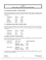
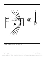
The IRIG-B Module is a status monitor card for the RFL 9785 which monitors input status every 1 ms.
Sequence Of Events are recorded when any point changes state or if the CPU gets reset. The Sequence Of
Events log is a record of the state of each point, the state of CPU reset, and the date and time the record was
saved. The system can record up to 40 events. The module has a free running clock which is synchronized every
ten seconds to the IRIG-B clock if IRIG-B is available. The SOE data is retrieved via a 3-wire RS-232 port.
Additional information on the RFL 9785 SOE/IRIG-B Module can be found in
of this manual.
2.7.9
VOICE MODULE
The Voice Module is part of the voice option available for the RFL 9785. It contains a microphone
amplifier, a signaling tone oscillator for sending signaling tones, a tone detector for receiving tones, a
voice demodulator and a speaker amplifier. Additional information on the RFL 9785 Voice Module
can be found in
of this manual.
2.7.10
CHECKBACK MODULE
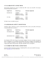
The RFL 9785 Checkback Module is a microprocessor based checkback system. Control and logic
signals are interfaced between the Checkback Module and the RFL 9785 system through the system
mother board. The Checkback Module is also connected to the SOE Module through the system
motherboard. The user can communicate with the Checkback Module by using the RS-232 connector
located on the RFL 9785 front panel, or by using the RS-232 connector located on the SOE I/O
Module (RFL 9785 rear panel). Additional information on the RFL 9785 Checkback Module can be
found in
of this manual.
2.7.11
CHECKBACK COMMUNICATIONS MODULE
The RFL 9785 Checkback Communications Module is used in some chassis in place of the SOE
Module, but only in chassis that have a Checkback module. Additional information on the RFL 9785
Checkback Communications Module can be found in
of this manual.
2.7.12
POWER SUPPLY MODULE
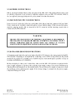
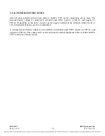
The RFL 9785 power supply accepts the incoming station battery voltage and produces four regulated
dc output voltages: +15 Vdc for the analog circuits, +5 Vdc for the logic circuits, and +12 Vdc for
powering the relays. Two different versions of the power supply are available: one for 38 to 150 Vdc
input, and one for 200 to 300 Vdc input. Additional information on the RFL 9785 Power Supply can
be found in
of this manual.
2.7.13
I/O MODULES
The I/O modules serve as an interface for input and output signals between the RFL 9785 and the line
coupling equipment. There are five types of I/O modules that can be used with the RFL 9785.
Additional information on the RFL 9785 I/O Modules can be found in
of this manual.

