19.3.2
CONTROLS AND INDICATORS
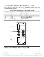
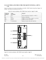
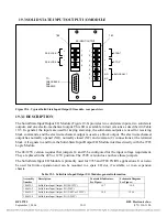
Figures 19-7 and 19-8 show the location of all controls and indicators on the Solid State Input/Output
I/O modules. These controls and indicators are described in Table 19-4. Only TB1, TB2 and P101 are
accessible with the Solid State Input/Output I/O module installed in the chassis. Jumpers J4 and J5 are
only accessible when the module is removed from the chassis or is on a card extender.
J9
J4
R20
TB1
L5
L6
L7
U2
R1
1
R1
5
R1
2
C8
C13
C15
C9
C10
C11
C12
CR9
CR10
CR11
CR12
R14
R13
R8
R7
R10
R1
9
C16
J8
R1
8
J5
L8
U1
R1
6
C7
C14
P1
K1
CR14
R9
R17
48V
125V
48V
125V
1
+
SS INPUT I/O 106438-1 REV-B
1N4761A
1N4761A
N/A
N/A
N/
A
11
3KV
.01uF
J
1
0
9
C
1
0
1
Q
1
0
2
U110
C
1
3
9
C
1
3
2
C
1
3
1
U
1
0
9
P101
C
R
1
0
5
C
1
3
0
U106
C
1
1
5
Q104
C
1
1
9
U108
C
1
2
5
C
1
2
9
C
1
2
6
C
1
2
8
C
1
2
7
C
R
1
0
4
U107
C
1
2
0
C
1
2
4
Q
1
0
6
C
1
2
1
C
R
1
0
6
T
1
0
2
Q
1
0
1
R
1
0
6
J
1
0
8
C
1
1
1
C
1
1
4
C
1
1
3
T
B
2
U
1
0
5
L104
L102
L101
C
R
1
0
1
C
1
1
2
C
R
1
0
2
T
1
0
1
U104
Q103
Q
1
0
5
C
1
3
5
C
1
3
3
U
1
0
2
C103
C104
C105
C
1
3
4
R
1
1
1
R
1
1
2
C
1
1
6
C
R
1
0
3
U103
R
1
1
0
R
1
0
3
R
1
0
4
L103
C
1
0
2
R
1
0
2
C
1
2
3
C
1
1
8
U101
R
1
0
1
R
1
0
8
C106
R
1
0
9
R
1
0
5
C
1
1
7
C
1
2
2
J
P
1
0
2
R
1
0
7
J
P
1
0
1
C
1
3
6
C
1
3
7
9780/85 SS OUTPUT I/O 106643 REV-B
BOONTON, NJ, USA 2000
RFL ELECTRONICS INC.,
S
D
G
1
S
D
G
1
J4
J5
TB-1
TB-2
P101
Figure 19-7. Controls/indicators, Solid State Input/Output I/O Modules (Assy. No. 106635-1 and -2)
RFL 9785
RFL Electronics Inc.
September 1, 2006
19-12
(973) 334-3100

