RFL 9785
RFL Electronics Inc.
March 1, 2013
xiv
(973) 334-3100
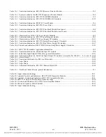
Table 12-1. Controls and indicators, RFL 9785 Receiver Detector Module...................................................................... 12-5
Table 13-1. Events recorded by the RFL 9785 Sequence of Events Module..................................................................... 13-2
Table 13-2. Controls and indicators, RFL 9785 SOE/IRIG-B module .............................................................................. 13-5
Table 13-3. Controls and indicators, RFL 9785 SOE/IRIG-B I/O module...................................................................... 13-12
Table 15-1. Controls and indicators, RFL9785 Voice Module .......................................................................................... 15-6
Table 15-2. Controls and indicators, RFL 9785 Voice Filter........................................................................................... 15-12
Table 16-1. Controls and indicators, RFL 9785 Checkback Module front panel .............................................................. 16-8
Table 16-2. Controls and indicators, RFL 9785 Checkback Module circuit board.......................................................... 16-10
Table 18-1. Characteristics of RFL 9785 Power Supply Modules..................................................................................... 18-2
Table 18-2. Controls and indicators, RFL 9785 power supply module ............................................................................. 18-5
Table 18-3. Characteristics of RFL 9785 Power Supply I/O modules............................................................................. 18-13
Table 18-4. Controls and indicators, RFL 9785 Single Power Supply I/O module ......................................................... 18-14
Table 18-5. Controls and indicators, RFL 9785 Dual Power Supply I/O module ........................................................... 18-17
Table 18-6. Controls and indicators, RFL 9780/85 External Amp Power Supply I/O module......................................... 18-21
Table 19-1. RFL 9785 I/O modules Application Information ........................................................................................... 19-2
Table 19-2. Controls and indicators, Solid State Input I/O module ................................................................................... 19-4
Table 19-3. Solid-State Input/Output I/O Modules, general information ........................................................................ 19-11
Table 19-4. Controls and indicators, Solid State Input/Output I/O modules (Assembly No. 106635-1, -2, -3, and –4) 19-14
Table 19-5. Alarm Outputs............................................................................................................................................... 19-23
Table 19-6. Controls and Indicators for RF Line I/O module.......................................................................................... 19-28
Table 19-7. Logic Straps .................................................................................................................................................. 19-33
Table 19-8. Logic Straps .................................................................................................................................................. 19-33
Table 19-9. Controls and Indicators, RFL 9785 Skewed Hybrid I/O. ............................................................................. 19-38
Table 21-1. Checkback Alarm Chassis, general information............................................................................................. 21-1
Table 22-1 Input Attenuator Settings ................................................................................................................................ 22-


