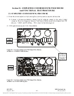
R10
R2
R16
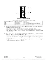
Figure 22-10. Potentiometer locations
Table 22-5 Controls and Indicators, RFL 9785 Power Amplifier Module
Component Designator
Name/Description
Function
R2 Potentiometer
Gain
adjustment
R10
Potentiometer
Low-Level Alarm Threshold voltage adjustment
R16
Potentiometer
Output impedance adjustment
7)
Check the Transmitter Fail Alarm by keeping the FSVM leads on the Output Filter Module TP1
and TP3 and keying the transmitter ON.
a)
For 10-watt applications, adjust R2 of the power amp for ~19Vrms (38.4dBm).
b)
Adjust R10 on the Power Amp such that the front panel TX Fail LED just barely turns ON.
c)
Re-adjust R2 on the Power Amp to the nominal 10-Watt 22.36 Vrms level. The TX Fail LED
should turn OFF.
8)
Check Carrier Output Impedance Matching by keeping the FSVM
leads to the Output Filter
Module TP1 (Brown – “COM”) and TP3 (White – “IN”).
a)
Note the position (A, B, or C) of Jumper J1 on the Output Filter module and remove the
jumper. See Step (Section 22. of Simplified Commissioning Procedure for 9785 Output Filter
Module diagram
.
b)
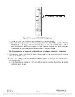
Key the transmitter ON 1-Watt by supplying keying voltage to the “RESERVE” keying input
on the SS I/O module, TB5-1 (+) to TB5-2 (-).
RFL 9785
RFL Electronics Inc
.
March 1, 2013
22-
11
(973) 334-3100


