RFL Electronics Inc.
March 2005
RFL 9785
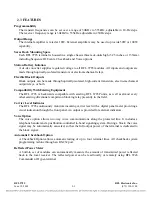
General
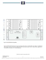
The 9785 is a programmable 10 W On/Off carrier system which
fully complies with ANSI C93.5. The system is packaged in a
single 3U high chassis and includes full-feature transmitter and
receiver sections. The unit can be optionally equipped with
voice capability and checkback functions. External amplifiers
can be used to boost the output power if required.
Dimensions: 19” x 5.25” x 15.25”
Supply voltage: 48/125 Vdc (38 to 150 Vdc 85 W)
250 Vdc (200 to 300 Vdc 85 W)
Approximate Weight: 17.5 lbs.
Operating Temperature:
-20°C to 60°C
Humidity: 0 to 95% non-condensing
ESD protection (per IEEE PC 37.90.3, 2001), Dielectric and
surge withstand: Per ANSI C93.5
Transmitter
The transmitter is a fully programmable Direct Digital Syn-
thesis (DDS) generator followed by a 10 W power amplifier
and filter. If the voice option is installed the audio signal is
AM modulated onto the carrier.
Frequency step size:
10 Hz
Frequency setting method:
Direct reading rotary switches
Rated output power:
10 Watts
Output impedance:
50 Ohms (with load-matching adjustment)
Carrier Level Indicator:
Display: Front panel 3-½ digit direct reading (in dB)
Range: ±10 dB
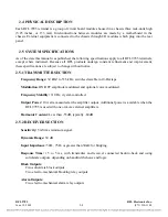
Optional Sequence of Events
System status points are checked every millisecond; changes
in system status (events) are recorded in the log with time
and date stamps. The events are stored in non-volatile memory
and are recalled most recent event first. The forty most re-
cent events are retained. The local clock is automatically syn-
chronized to an externally supplied IRIG-B signal if available.
IRIG-B input:
1000 Hz modulated or direct TTL
Signals monitored:
See Table 1.
Output Ratings
Solid State Outputs
Maximum continuous current:
1 Amp
Maximum 1 minute current:
2 Amps
Maximum 100 mSec current:
10 Amps
Maximum open circuit voltage:
280 Volts
Trip Relay Outputs
Maximum continuous current:
5 Amps
Maximum 200 mSec current:
30 Amps
Maximum open circuit voltage:
280 Volts
Alarm Relay Outputs
Maximum continuous current:
1 Amp
Maximum breaking current (125 Vdc):
1 Amp,
non-inductive
Maximum breaking current (280 Vdc):
0.25 Amp,
non-inductive
Maximum open circuit voltage:
280 Volts
Note:
Logic level (5 volt nominal ) outputs are available.
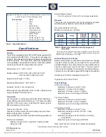
Point Number
9785
1 ......................... Start
2 ......................... Stop
3 ......................... Reserve Key
4 ......................... Remote Initiate
5 ......................... Transmitter Fail
6 ......................... Checkback Fail
7 ......................... Block Output
8 ......................... Power Up
9 ......................... Power supply # 1 fail
10 ...................... Power supply # 2 fail
Sequence Of Events Log for the Tx/Rx provides a record for 40
events for each of the following points
Table 1. Signals Monitored
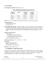
Table 2. Minimum permissible channel spacings and
delay times.
Specifications
*
The delay times specified have been established per ANSI C93.5,
section 5.7.3, and 6.3.21. The electromechanical block output con-
tacts will add an additional 7 ms delay.
3
External Meter Output:
0 to 100
µ
Amp ±1 Volt or 0-5 Volt, jumper selectable.
Receiver
The receive circuit consists of an input normalizer, program-
mable frequency detector, and carrier level indicator.
Receiver sensitivity: 5 mVrms
Maximum receive level: >25 Vrms
1 kHz
2 kHz
3 kHz
4 kHz
4 kHz
4 kHz
5 ms
3 ms
1.5 ms
500 Hz
1000 Hz
1500 Hz
Nominal
Bandwith
Delay
Channel
Spacing
w/Voice
Channel
Spacing
w/o Voice
*
Specifications subject to change without notice.

