7.4.1
FREQUENCY SELECT SWITCHES
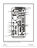
Up to three carrier frequencies can be preset, depending on the system configuration. The center
frequency is set using a set of five rotary DIP switches arranged as “XXX.XX Khz” (SW3-SW7). The
shift up frequency is set using two rotary DIP switches arranged as “0.XX Khz” (SW8 and SW9). The
shift down frequency is set using two rotary DIP switches arranged as “0.XX Khz” (SW1 and SW2).
This allows the frequency to be set to within 10 Hz. Only settings between 30 Hz and 535 Khz are
valid.
7.4.2
TRANSMIT AMPLITUDE POTENTIOMETER
Potentiometer R23 is used to set the transmit amplitude of the module to achieve the proper output
power, while compensating for variations in installation and setup. The system is normally set to a
10W output, but this setting is automatically scaled down to 3W or 1W as required.
7.4.3
RESERVE LEVEL JUMPER
In systems which use the reserve feature, the reserve level can be fixed at 10% or can be variable
between approximately 10% and 35% of the power level. When jumper J2 is in the “VAR” position,
R18 is used to adjust the reserve level.
RFL 9785
RFL Electronics Inc.
April 25, 2005
7-7
(973) 334-3100


