9.2.5.3.4
DUMMY LOAD
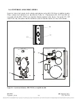
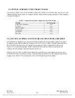
An external Dummy Load and Attenuator Board are provided as described in Paragraph 9.2.7. To
observe the signal going to the line coupling equipment use test points TP1 and TP2.
9.2.5.3.5
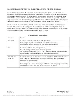
IMPEDANCE MATCHING TRANSFORMERS
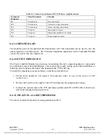
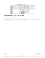
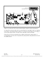
Impedance matching transformers T1 and T2 match the impedance of the Line Board to that of the
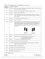
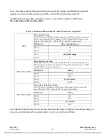
line. Jumper J10 selects one of T1’s four impedance settings: 50, 75, 100, or 130 ohms. Fuse F1
provides current protection, and surge arrestor E2 protects the equipment against an overvoltage
condition. Jumper J20 selects one of T2’s four impedance settings: 50, 75, 100, or 130 ohms. Fuse F2
provides current protection, and surge arrestor E1 protects the equipment against an overvoltage
condition. In 2 wire applications, the signal going to or coming from the line coupling equipment can
be monitored at test point TP2. In 4 wire applications, the signal going to the line coupling equipment
can be monitored at test point TP2, and the signal coming from the line coupling equipment can be
monitored at test point TP3.
RF From/To
Line Coupling
Equipment
Transmit Input 1
From Power Amp 1
Transmit Input 2
From Power Amp 2
(when used)
Complex
Balance
Network
Hybrid
Transformers
Impedance
Matching
Transformers
Receive
Attenuator
Surge
Arrestors
IN J11
OUT
Receive
Output
To
Rx
Filter
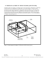
Figure 9-10. Block diagram, RFL 9508 Line Board
RFL 9785
RFL Electronics Inc.
May 16, 2011
9-13
(973) 334-3100

