RFL 9785
RFL Electronics Inc.
June 18, 2009
2-8
(973) 334-3100
2.7.2
TRANSMITTER MODULE
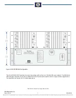
The 9785 Transmitter Module utilizes Direct Digital Synthesis (DDS) to generate precise carrier signals. The
desired frequency is selected by a bank of direct reading switches. There are three banks of switches so that a
single Transmitter Module can be used in a three frequency application.
The Transmitter Module can amplitude modulate the carrier to an analog voice signal if the input system is
equipped with this option. The output section of the module adjusts the amplitude to provide the desired output
power. Additional information on the RFL 9785 Transmitter Module can be found in
of this manual.
2.7.3
POWER AMPLIFIER MODULE
The RFL 9785 Power Amplifier is driven by the transmitter module, and raises the power of the transmitter to
the level chosen for the application. It also includes a level monitoring circuit that will send a TX FAIL alarm to
the logic module if the transmitter fails. The amplifier has a transformer-isolated output, and a 50
Ω
output
impedance. Additional information on the RFL 9785 Power Amplifier Module can be found in
manual.
2.7.4
RFL 9508 RF CHASSIS
For details on the 50 and 100 Watt PowerAmplifers used with the RFL 9785 see
2.7.5
OUTPUT FILTER MODULES
RFL 9785 Output Filter modules are used to reduce the harmonic content of the Power Amplifier’s output signal
to a level that is at least 55 dB below the carrier level. In order to cover the RFL 9785's entire operating range
(30kHz to 535 kHz), there are four different RFL 9785 Output Filters. Three filters are equipped with jumpers
for selecting the desired frequency range and the fourth has a fixed range, which covers the top of the RFL
9785's frequency band. All four filters are entirely passive, and require no input power for proper operation.
Additional information on the RFL 9785 Output Filter Modules can be found in
of this manual.
2.7.6
RECEIVER DOWNSHIFTER MODULE
The RFL 9785 Receiver Downshifter Module accepts incoming rf signals which are shifted down to 24 kHz. Its
channel filter is 3700 Hz wide, which will pass carrier signals or voice sidebands of the carrier, if present.
Additional information on the RFL 9785 Receiver Downshifter Module can be found in
of this
manual.
2.7.7
RECEIVER DETECTOR MODULE
The RFL 9785 Receiver Detector Module contains three elements of the RFL 9785's receiving system: A
narrowband active band-pass filter that sets the bandpass limits for the entire receiving section, a carrier detect
circuit used to signal the AM Logic Module that a signal is being received, and a digital meter to indicate
deviation of the received signal above or below the specified normal level. Additional information on the RFL
9785 Receiver Detector Module can be found in
of this manual.

