4.8
INITIAL START-UP PROCEDURE
NOTE
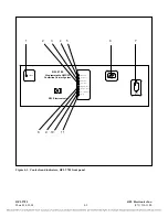
DURING SHIPPING, THE MODULES IN THE CHASSIS MAY BACK OUT OF
THEIR CONNECTORS. PRIOR TO BEGINNING THE STARTUP PROCEDURE,
OPEN THE FRONT DOOR, AND REMOVE AND RE-SEAT ALL FRONT PANEL
MODULES.
After the 9785 is installed and prior to being placed in service, a few basic adjustments and
measurements must be performed to ensure proper operation. The output power of the system should
be verified and adjusted if required, the output impedance of the transmitter must be adjusted to match
the actual impedance of the line, and the receiver must be adjusted for the actual receive signal level.
This section assumes that the equipment has been installed and configured for the required application
in accordance with Section 3 and paragraph 4.3. Note that the modules in the 9785 are not hot
pluggable. The power to the chassis must be turned off prior to removing in or installing any modules.
4.8.1
EQUIPMENT REQUIREMENTS
The following equipment is required to perform the initial startup procedures:
1.
Frequency-selective voltmeter (FSVM)
2.
Potentiometer adjustment tool (or small flat-blade screwdriver)
3.
50 ohm (non-inductive) dummy load
4.
PLC Test Set (Signal Crafters Model 70 or equivalent)
5.
Optional module extender card (RFL part number 9547-1870)
4.8.2
TRANSMITTER
It is advisable to verify the operation of the transmitter after installation into the system. This allows
checking the 9785 and line tuning equipment.
RFL 9785
RFL Electronics Inc.
March 24, 2008
4-12
(973) 334-3100

