19.5
RF LINE I/O MODULE
1
2
3
4
5
6
7
8
9785 RF LINE I/O
1
2
3
4
J5
TX
J7
RX
TX
RX
EXT METER
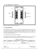
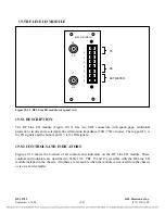
Figure 19-13. RFL Line I/O module, rear panel view
19.5.1
DESCRIPTION
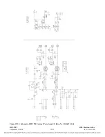
The RF Line I/O module (Figure 19-13) has two UHF connectors with spark gaps, additional
protection circuits and a selectable line termination impedance (50
Ω
, 75
Ω
or none). The top port J5, is
for TX signals and the bottom port J7, is for RX signals.
19.5.2
CONTROLS AND INDICATORS
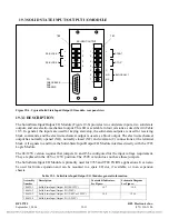
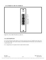
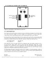
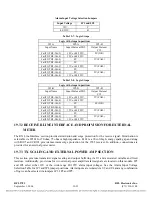
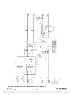
Figure 19-14 shows the location of all controls and indicators on the RF Line I/O module. These
controls and indicators are described in Table 19-6. TB1, J5 and J7 accessible with the RF Line I/O
module installed in the chassis. All others are accessible when the module is removed from the chassis
or is on a card extender.
RFL 9785
RFL Electronics Inc.
September 1, 2006
19-27
(973) 334-3100

