12.4
CONTROLS AND INDICATORS
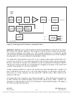
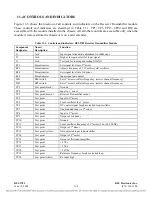
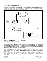
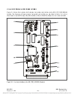
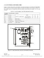
Figure 12-3 shows the location of all controls and indicators on the RFL 9785 Receiver Detector
module. These controls and indicators are described in Table 12-1. Only R26 and R34 are accessible
with the RFL 9785 Receiver Detector module installed in the chassis. All others are accessible when
the module is removed from the chassis or is on a card extender.
Table 12-1. Controls and indicators, RFL 9785 Receiver Detector Module
Component
Name/Description Function
Designator
DPM1
Digital Panel Meter
Displays signal level in dB.
J1
Connector
Input to voice bandpass filter (when voice filter is plugged in)
J2
Connector
Output
of voice bandpass filter (when voice filter is plugged in)
Position “A” selects
±
1 Vdc output.
J3
Jumper
Position “B” selects 0 to -100
μ
A output.
Position “C” selects 0 to -5 Vdc output.
R26
Potentiometer
Sets the signal level threshold
R34
Potentiometer
Sets the signal level meter to zero dB (meter null)
R51
Potentiometer
Calibrates the meter signal
R67
Potentiometer
Narrow Band filter adjust
R74
Potentiometer
Narrow Band filter adjust
R79
Potentiometer
Narrow Band filter adjust
R84
Potentiometer
Ripple
adjust
R90
Potentiometer
Sets the signal level at the output of the narrow-band filter (output gain)
TP1
Test Point
Signal ground
TP2
Test Point
Input to voice filter
TP3
Test Point
Output of voice filter
TP4
Test Point
Output of logarithmic amplifier
TP5
Test Point
Output of signal level detector and filter
TP6
Test Point
Signal applied to Digital Panel Meter
TP7
Test Point
Input to bandpass filter
TP8
Test Point
Output of bandpass filter
TP10
Test Point
Level out
TP11
Test Point
Signal ground
TP12
Test Point
Used to monitor the threshold for carrier detect (for factory use only)
TP13
Test Point
+5VDC reference
TP14
Test
Point
-5VDC
>> text continues on page 12-7 <<
RFL 9785
RFL Electronics Inc.
July 7, 2006
12-5
(973) 334-3100


