13.3
SEQUENCE OF EVENTS/IRIG-B I/O MODULE
TB1
E6
C6
C2
C5
E5
E4
E3
E2
J1
J3
R1
R5
R2
R3
CR6
CR9
CR4
CR8
CR7
CR1
C9
C12
C13
C14
C15
C16
C10
C4
C1
C7
T1
CR5
C3
C17
CR10
E1
J4
J2
P2
R4
TP1
P1
CR3
CR2
C11
C8
OUT
OUT
OUT
IN
IN
IN
6
9
5
1
.002uF
.002uF
.001uF
221
100
221
221
400CA
1.5KE
400CA
1.5KE
P6KE
16CA
16CA
P6KE
16CA
P6KE
P6KE 30CA
1KV
.0068uF
.01uF
.002uF
.001uF
.001uF
XFM
R
P
1200
(95595)
P6KE6.8
.001uF
SB160
101691
101106
221
16CA
P6KE
30CA
P6KE
1KV
.0068uF
.002uF
.01uF
.01uF
103312
103312
103312
103312
103312
103312
.01uF
.01uF
.01uF
.01uF
SOE
IR
IG
-B
R
S
-2
3
2
13-5a
13-5b
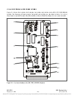
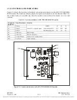
Figure 13-4. Board and panel views of RFL 9785 SOE/IRIG-B I/O module
13.3.1
DESCRIPTION
The RFL 9785 SOE/IRIG-B I/O module provides an interface between the IRIG-B receiver and the
RFL 9785 SOE/IRIG-B module. It has provisions for modulated (bipolar) or demodulated (TTL)
IRIG-B inputs, and provides an RS-232 connector to access the sequence of events log. The modulated
(bipolar) signal is a 1 kHz amplitude modulated signal (0-3Vp-p) representing seconds, minutes, hours
and days. The demodulated (TTL) signal is a 0 to 5Vdc data message representing seconds, minutes,
hours and days. A board view of the module is shown in Figure 13-5a, and a rear panel view is shown
in Figure 13-5b.
RFL 9785
RFL Electronics Inc.
December 7, 2009
13-11
(973) 334-3100


