Section 11.
RECEIVER DOWNSHIFTER MODULE
C87
P1
TP15
U2
R5
2
TP12
TP19
R5
3
TP14
C91
C8
6
R54
R55
C94
C7
1
L8
U12
C8
3
R5
0
R5
1
R63
R28
C3
6
C6
9
U11
C81
TP17
R49
L10
Y1
CR3
CR4
C5
C2
7
U14
Y2
C76
C75
C93
C74
C3
8
CR2
C82
TP11
TP10
TP9
TP8
TP7
TP6
TP5
R1
5
R10
U7
U6
TP1
TP3
R48
R4
2
R45
R43
R44
R4
0
R3
9
R3
8
R3
7
R3
6
R3
5
R3
4
R33
R3
2
R3
1
R2
9
R3
0
R2
4
R2
7
R2
5
R2
6
R2
3
R2
2
R1
9
R1
8
R2
1
R2
0
R1
7
R1
6
R1
3
R1
2
R1
4
R1
1
R9
R8
R7
R6
R5
R4
R1
R2
R3
R4
7
L2
L6
L7
L3
L5
C4
C77
TP18
C31
C3
3
C3
2
C55
C28
C26
C8
0
C79
C7
8
R56
C6
8
C6
7
C56
C57
C60
C6
1
C8
4
C5
9
C63
C62
C5
8
C6
4
C44
C45
C46
C49
C51
C50
C48
C5
4
C52
C47
C5
3
C4
0
C3
9
C3
5
R60
C1
9
C2
0
C8
C11
C16
C12
C10
C14
C13
C9
L11
C7
0
C6
6
C4
3
C4
2
C4
1
C3
7
C30
C2
4
C2
2
C2
3
C18
C17
C6
C7
C3
C2
TP13
J3
U10
U8
C6
5
R66
Q1
U5
C3
4
CR1
C29
U4
SW2
U3
TP4
TP2
R65
FL101
U1
C8
5
R41
C92
R46
C9
5
L4
L1
C25
C1
5
C1
C90
C89
C88
C2
1
L9
U13
R59
R58
R57
J1
U9
C99
C9
7
C
100
C
101
C
103
C
102
C98
J2
R64
R62
R61
R70
U15
R67
R69
TP20
R68
C9
6
C
104
C
105
C73
TP16
9785 RX DOWNSHIFTER ECB NO 106578 REV E
GAIN
GAIN
LO
HI
50
40
30
20
10
ATTEN
dB
0
1999 RFL ELECTRONICS INC., BOONTON, NJ, U.S.A.
.25
.5
1
2
4
8
16
32
64
128
256
512
KHZ
32
A
C
1
+
+
+
+
+
+
+
+
+
1
+
+
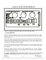
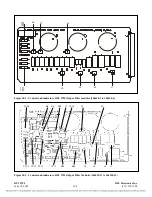
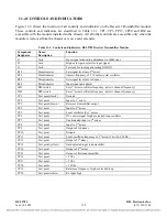
Figure 11-1. RFL 9785 Receiver Downshifter Module
11.1
DESCRIPTION
The RFL 9785 Receiver Downshifter Module (Figure 11-1) is used to shift the desired set of incoming
rf signals down to a lower range, around 24 kHz, to be further processed by the receiver detector
module (Section 12). Its channel filter, which is 3700 Hz wide, will pass carrier signals or voice
sidebands of the carrier, if present. The Downshifter Module contains a set of DIP switches which
allow a user to program the desired receive frequency.
For specific component information at the board level please contact the factory with the board
part number and revision level.
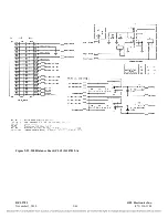
Receiver Downshifter Module Schematics are provided at the end of
this section.
RFL 9785
RFL Electronics Inc.
June 18, 2009
11-1
(973) 334-3100


