19.3
SOLID STATE INPUT/OUTPUT I/O MODULE
SS INPUT/OUTPUT
1
2
3
4
5
6
7
1
2
3
4
+
-
+
-
SS BLOCK 1
SS BLOCK 2
+
-
+
-
C
NO BLOCK RLY 1
NC
START
STOP
TB1
TB2
TO
CHECKBACK
AUX
CHASSIS
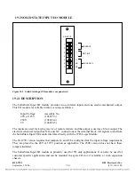
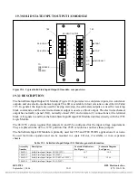
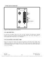
Figure 19-6. Typical Solid State Input/Output I/O module, rear panel view
19.3.1
DESCRIPTION
The Solid-State Input/Output I/O Module (Figure 19-6) provides two solid state inputs, two solid state
outputs, and one electro-mechanical output. This I/O is available in four versions as described in Table
19-3. In general, the inputs are used for keying start/stop, the solid-state outputs are used for receiving
block commands, and the electro-mechanical output is used as a block output. The electro-mechanical
output has normally opened (NO), normally closed (NC) and common (C) connections at the terminal
block. All signals to and from the Solid-State Input/Output I/O Module interface directly with the 9785
Logic Module.
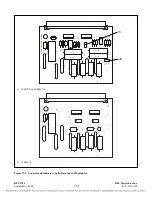
The 48/125V version requires that jumpers J4 and J5 be configured for the input voltage requirement.
They are placed in the 48V or 125V position. The 250V version does not have these jumpers.
The Solid-State Input I/O Module is primarily used for 9785 and 9780 TX/RX applications. It can also
be
used for future expansion and can be mounted in a spare I/O slot, if available, or in an expansion
chassis.
Table 19-3. Solid-State Input/Output I/O Modules, general information
Assembly
Number
Description
Controls & Indicators,
See Figure:
Schematic Diagram
See Figure:
106635-1
Solid-State Input/Output I/O (48/125V)
RFL 9785
RFL Electronics Inc.
September 1, 2006
19-11
(973) 334-3100
19-9
106635-2
Solid-State Input/Output I/O (250V)
19-7
106635-3
Solid-State Input/Output I/O (5/48V or 5/125V)
19-8
19-10
106635-4
Solid-State Input/Output I/O (5/250V)


