Section 16.
CHECKBACK MODULE
PASS FAIL
CODE CODE
RCVD SENT
HOURS HOURS TO
BETWEEN NEXT
TEST TEST
RUN PASSED
TEST
FAIL
DISPLAY
SELECT
RESET
LOG
UP
DWN
START TEST
HC1
HC3
HC2
HC4
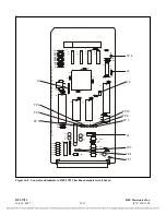
Figure 16-1. RFL 9785 Checkback Module, front panel view
16.1
DESCRIPTION
The RFL 9785 Checkback Module (Figure 16-1) is a microprocessor based checkback system. Control
and logic signals are interfaced between the Checkback Module and the RFL 9785 system through the
system mother board. The Checkback Module is also connected to the SOE Module or the Checkback
Communications Module through the system motherboard. The user can communicate with the
Checkback Module, if equipped, by using the RS-232 connector located on the RFL 9785 front panel,
or by using the RS-232 connector located on the SOE I/O Module (RFL 9785 rear panel).
The front panel of the RFL 9785 Checkback Module serves as the local operator interface. It has
pushbutton switches which allow the entry of operating parameters and control functions. A 3-digit
LED display shows operating parameters, and LED annunciators display pertinent system data.
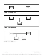
The Checkback Module can perform powerline carrier functionality testing on multi-terminal lines.
Figures 16-2 through 16-4 are examples of multi-terminal configurations that can be tested by the
Checkback Module.
RFL 9785
RFL Electronics Inc.
July 26, 2007
16-1
(973) 334-3100


