3 – Managing Fabrics
Managing the Fabric Database
59226-00 B
3-7
A
3.3.6
Deleting Switches and Links
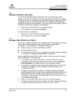
The SANsurfer Switch Manager application does not automatically delete
switches or links that have failed or have been physically removed from the fabric.
In these cases, you can delete switches and links to bring the display up to date. If
you delete a switch or a link that is still active, the SANsurfer Switch Manager
application will restore it automatically. You can also refresh the display. To delete
a switch from the topology display, do the following:
1.
Select one or more switches in the topology display.
2.
Open the Switch menu and select
Delete
.
To delete a link, do the following:
1.
Select one or more links in the topology display.
2.
Open the Switch menu and select
Delete
.
3.3.7
Adding a New Switch to a Fabric
If there are no special conditions to be configured for the new switch, simply plug
in the switch and the switch becomes functional with the default fabric
configuration. The default fabric configuration settings are:
Fabric zoning is sent to the switch from the fabric.
All ports will be GL_Ports.
The default IP address 10.0.0.1 is assigned to the switch without a gateway
or boot protocol configured (RARP, BOOTP, and DHCP).
If you are adding a new switch to a fabric and do not want to accept the default
fabric configuration, do the following:
1.
If the switch is not new from the factory, reset the switch to the factory
configuration before adding the switch to the fabric by selecting
Restore
Factory Defaults
in the Switch menu from the faceplate display.
2.
If you want to manage the switch through the Ethernet port, you must first
configure the IP address using the Network Properties dialog or the
Configuration Wizard.
3.
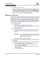
Configure any special switch settings. Consider configuring the Default
Visibility setting to None in the Zoning Config dialog to prevent devices from
finding other devices on all switches in the fabric until the new switch is
configured. To open the Zoning Config dialog, open the Zoning menu, and
select
Edit Zoning Config
.
4.
Plug in the inter-switch links (ISL), but do not connect the devices.
5.
Configure the port types for the new switch using the Port Properties dialog.
The ports can be G_Port, GL_Port, F_Port, FL_Port, or Donor.
Summary of Contents for SANbox 1400 Series
Page 12: ...Page xii 59226 00 B SANbox 1400 Series Switch Management User s Guide S Notes...
Page 126: ...4 Managing Switches Displaying Hardware Status 4 38 59226 00 B S Notes...
Page 154: ...5 Managing Ports Graphing Port Performance 5 28 59226 00 B S...
Page 265: ...A Command Line Interface Zoning Command 59226 00 B A 111 A...
Page 266: ...A Command Line Interface Zoning Command A 112 59226 00 B S Notes...

