background image

7  Testing and Maintenance

72

inspection, testing or analysis, as specified in the IEC 60601-1:2005+A1:2012/EN 60601-
1:2006+AC:2010 or in this book.
Medical electrical equipment must comply with the requirements of the general standard IEC/
EN 60601-1, its relevant particular standards and specific national deviations. Non-medical electrical 
equipment shall comply with IEC and ISO safety standards that are relevant to that equipment.
Relevant standards for some non-medical electrical equipment may have limits for equipment leakage 
currents higher than required by the standard IEC 60601-1:2005+A1:2012/EN 60601-
1:2006+AC:2010. These higher limits are acceptable only outside the patient environment. It is 
essential to reduce equipment leakage currents when non-medical electrical equipment is to be used 
within the patient environment.

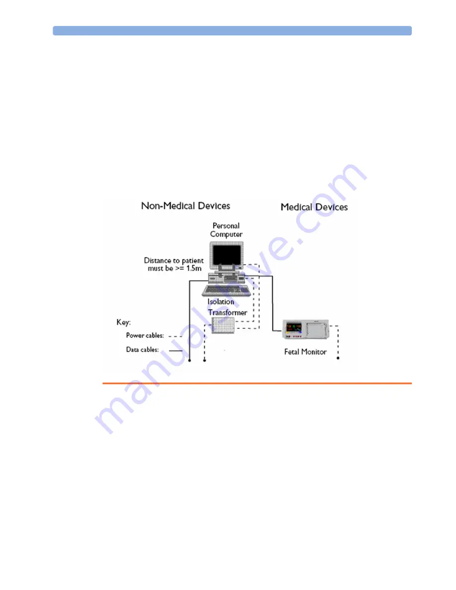
System Example

This illustration shows a system where both the medical electrical equipment and the non-medical 
electrical equipment are situated at the patient’s bedside.

WARNING

Do not use additional AC mains extension cords or multiple portable socket-outlets. If a multiple 
portable socket-outlet is used, the resulting system must be compliant with IEC 60601-
1:2005+A1:2012/EN 60601-1:2006+AC:2010. Do not place multiple socket-outlets on the floor. 
Do not exceed the maximum permitted load for multiple socket-outlets used with the system. Do 
not plug additional multiple socket-outlets or extension cords into multiple socket-outlets or 
extension cords used within the medical system

Do not connect any devices that are not supported as part of a system.

Do not use a device in the patient vicinity if it does not comply with IEC/EN 60601-1. The whole 
installation, including devices outside of the patient vicinity, must comply with IEC 60601-
1:2005+A1:2012 / EN 60601-1:2006+AC:2010. Any non-medical device, 

including a PC 

running an OB TraceVue/IntelliSpace Perinatal system

, placed and operated in the patient’s 

vicinity must be powered via a separating transformer (compliant with IEC 60601-

Summary of Contents for Avalon FM20

Page 1: ...Service Guide Avalon Fetal Monitor FM20 FM30 Release J 3 with Software Revision J 3x xx Fetal Monitoring ...

Page 2: ......

Page 3: ...Mains 29 Disconnecting the Monitor from AC Mains 30 Connecting the Monitor to Non Medical Devices 30 Installing the Tympanic Thermometer 31 Before Using the Monitor 35 4 Theory of Operation 39 Monitor Hardware Overview 39 Power Supply 40 Connector Block 40 Bus Master Board 40 Main CPU Board 40 I O Boards 41 Fetal Recorder Thermal Printer Unit 41 LCD Display and Touchscreen 42 Noninvasive Blood Pre...

Page 4: ...tions 55 Recommended Frequency 56 When to Perform Tests 56 Testing Sequence 58 Visual Inspection 59 Safety Tests 59 System Test 71 Preventive Maintenance Procedures 82 Performance Assurance Tests 83 Reporting of Test Results 87 Other Regular Tests 91 Battery Handling Maintenance and Good Practices 99 After Installation Testing or Repair 104 8 Troubleshooting 105 Who Should Perform Repairs 105 Repl...

Page 5: ...ing Upgrade Options 215 Software and Firmware Upgrades 222 12 Specifications 223 Environmental Specifications 223 Physical Specifications 224 Interface Specification 226 Performance Specifications 227 Recorder Specifications 238 Manufacturer s Information 240 Trademark Acknowledgment 240 Regulatory and Standards Compliance 240 Environment 249 Monitoring After a Loss of Power 250 ESU MRI and Defibr...

Page 6: ...6 ...

Page 7: ...ions for Use Refer to the Instructions for Use for maintenance and troubleshooting procedures that may be performed during normal operation Only qualified and authorized service personnel should attempt to install the system disassemble the monitor remove or replace any internal assemblies or replace the transducer cable or belt buttons For detailed information concerning the configuration of the ...

Page 8: ...y the main CPU board the bus master board the socket connector block the transducer cable the transducer belt button See Parts on page 125 for part numbers and Repair and Disassembly on page 139 for repair details Repair or replacement of individual components on the boards is not supported and should never be attempted For tests that you are required to perform after repairs refer to When to Perf...

Page 9: ...or configuration Safety Information Warnings and Cautions In this guide A warning alerts you to a potential serious outcome adverse event or safety hazard Failure to observe a warning may result in death or serious injury to the user or patient A caution alerts you where special care is necessary for the safe and effective use of the product Failure to observe a caution may result in minor or mode...

Page 10: ...ices that are not supported as part of a system Any non medical device placed and operated in the patient s vicinity must be powered via an approved isolation transformer that ensures mechanical fixing of the power cords and covering of any unused power outlets Do not use USB devices with own power supplies unless an appropriate separation device is used either between USB interface and device or ...

Page 11: ...liquid on the monitor contact your service personnel or Philips service engineer Never immerse the fetal monitor or the CL base station in liquid You must protect them against water sprays or splashes Place the fetal monitor and the CL base station where there is no chance of contact with or falling into water or other liquids Do not perform underwater monitoring for example in a bath or shower us...

Page 12: ...s approved accessories Using non Philips approved accessories may compromise device functionality and system performance and cause a potential hazard Reuse Never reuse disposable transducers sensors accessories and so forth that are intended for single use or single patient use only Reuse may compromise device functionality and system performance and cause a potential hazard Electromagnetic compat...

Page 13: ... run power cables through the same conduit or trunking used for system cables Maintenance Repair and Care WARNING Maintenance and Repair Do not maintain or repair the device in patient vicinity Failure on the part of the responsible individual hospital or institution using this equipment to implement a satisfactory maintenance schedule may cause undue equipment failure and possible health hazards ...

Page 14: ...ispose of the battery in accordance with the disposal instructions above Keep batteries out of the reach of children Do not disassemble heat above 100 C 212 F or incinerate the batteries to avoid the risk of fire and burns Keep batteries in their original package until you are ready to use them Do not install or use pre damaged batteries Care and Disinfection To avoid contaminating or infecting pe...

Page 15: ...cation of the various system components Environment Confirming and correcting as necessary the environment of the proposed installation site s System Capabilities Explaining the possibilities for system expansion Mounting Referencing the mounting hardware information website for the listing of suitable mounting hardware recommended for use with the various system components and all details on the ...

Page 16: ...which is required to install the mounting hardware supplied by Philips as detailed in the installation notes Making sure that all ceilings walls and mounting rails that supports mounting hardware are suitable for their proposed load WARNING It is the customer s responsibility to have the attachment of the mounting hardware to the ceiling wall or mounting rail and the construction of the ceiling wa...

Page 17: ...evious section Site Requirements The site requirements are listed in this section Space Requirements The situating of the monitor should be planned such that the nursing staff are able to monitor the patient with relative ease with all patient connectors and controls readily available and the displays clearly visible The location should also allow access to service personnel without excessive disr...

Page 18: ...C 32 F 113 F with fully charged battery 0 C 40 C 32 F 104 F with battery charging 0 C 35 C 32 F 95 F Storage 20 C 60 C 4 F 140 F Humidity Range Operating 95 relative humidity 40 C 104 F Storage 90 relative humidity 60 C 140 F Altitude Range Operating 500 3 000 m 1 640 9 840 ft Storage 500 13100 m 1 640 to 43 000 ft Transducers M2734A M2734B M2735A M2736A M2738A Temperature Range Operating 0 C 40 C...

Page 19: ... or Philips Line Voltage Connection The FM20 FM30 monitor uses supply voltage 100V 240V 0 7A 0 4A The M8023A External Power Supply uses supply voltage 100V 240V 1 3 0 7A The FM20 FM30 monitor and the M8023A External power supply may be operated with supply frequency range of 50 Hz to 60 Hz Essential Performance This section defines the essential performance for Avalon fetal monitors in combination...

Page 20: ...ot provided NBP Measurement of non invasive systolic diastolic and mean blood pressure and pulse rate within specified accuracy and error limits Automatic cycling Alarming on limit violations of systolic diastolic and mean blood pressure and pulse rate SpO2 Measurement of oxygen saturation and pulse rate within the specified accuracy error limits Alarming on oxygen saturation and pulse rate limit ...

Page 21: ...inity must be powered via a separating transformer compliant with IEC 60601 1 2005 A1 2012 EN 60601 1 2006 AC 2010 that ensures mechanical fixing of the power cords and covering of any unused power outlets Do not connect any devices that are not supported as part of a system Whenever you combine equipment to form a system for example connecting the monitor to an OB TraceVue system IntelliSpace Per...

Page 22: ...uirements for Connection to OB TraceVue IntelliSpace Perinatal For cabling options and requirements for connection to an OB TraceVue IntelliSpace Perinatal system refer to the OB TraceVue IntelliSpace Perinatal Site Preparation Guide and the OB TraceVue IntelliSpace Perinatal Service Guide ...

Page 23: ... Mount Flush wall mount for flat wall mounting M2740 64002 451261009071 M2740A A05 MECHASY Wall Mounting arm with tray M2740 64005 451261009101 M2740A R01 MECHASY Roll Stand with tray 5061 8324 451261009111 M2740A W01 MECHASY Wall Channel 19 n a n a M2740A C02 Cart with fixed angle mount and two drawers n a n a M2740A U01 Mounting kit for Avalon CL Avalon CTS for use with M2740A C02 ...

Page 24: ...terface n a n a M2740A B01 Bed hanger Part Number 12NC Product Option Number Description Product Option Number Part Number 12NC Part Number Description M8024A A01 862454 9898 031 24741 Slimline keyboard with integrated trackball M8024A B01 M4046 60104 4512 610 00661 Optical mouse USB PS 2 M8024A C01 M4046 60103 4512 610 00651 Wired track ball USB PS 2 M8024A C02 M4046 60105 4512 610 00671 Wireless...

Page 25: ...s Please contact your local Philips sales representative for details of availability Please keep the packing materials until you have completed the initial inspection in case there is a defect on arrival Installation Checklist Fetal Monitor Use this checklist to document your installation Step Task Check when done 1 Perform initial inspection of delivery unpack and check the shipment see Unpacking...

Page 26: ...g Recorder Speed on page 36 8 Perform system test as necessary see Performance Assurance Tests on page 83 9 For monitors with the battery option E25 confirm that the battery can be charged and that the monitor can be powered by the battery 10 Test transducers see Transducers and Patient Modules Functional Tests on page 91 Step Task Check when done System Components Accessories and Supplies FM20 FM...

Page 27: ...s of the owner the instrument model and serial numbers and the repair required or symptoms of the fault Resend the device only in safe condition and make sure that it is decontaminated If available and reusable the original Philips packaging should be used to provide adequate protection during transit If the original Philips packaging is not available or reusable please contact the Philips sales s...

Page 28: ...ounting hardware to the ceiling wall or mounting rail and the construction of the ceiling wall or mounting rail evaluated for structural integrity and compliance with all local state and any other required codes by a registered professional structural and or mechanical engineer Ensure that this commitment has been met before assembling mounts Mounting the External Power Supply M8023A The external ...

Page 29: ...ve earth conductor is required for EMC purposes It has no protective function against electric shock The protection against electric shock in this device is provided by double and or reinforced insulation Do not use AC mains extension cords or multiple portable socket outlets Always ensure that the monitor is positioned so that the AC mains plug is easily accessible to allow disconnection of the m...

Page 30: ...wer cords and covering of any unused power outlets Disconnecting the Monitor from AC Mains FM20 30 To disconnect the monitor from AC power switch the monitor off using the On Off switch located on the right side of the device or unplug the power cord from the AC mains socket FM20 FM30 with Battery Option The On Standby button does not disconnect the monitor from the AC power source To disconnect u...

Page 31: ...n cable through one of the channels 2 in the base station 2 Attach the mounting plate or mounting clamp to the base station See Mounting the Tympanic Thermometer on page 33 for details 3 Insert the thermometer cable into the base station by aligning the white arrows on the cable connector and the base station 4 Route the cable through the strain relief 1 in the base station ...

Page 32: ...o the MIB RS232 1 port of the monitor 8 Configure the MIB R232 port at the fetal monitor to iTemp Switch to the Service Mode Select the Main Setup SmartKey to open the Main Setup window and select Hardware from the menu In the Setup Hardware window select Interfaces In the Setup Interfaces window select iTemp for the MIB R232 port NOTE When disconnecting the thermometer cable from the base station...

Page 33: ...tional mode settings in biotech mode are stored in nonvolatile memory and retained through system power cycles such as changing batteries All factory calibration parameters are also stored in nonvolatile memory The factory default settings are shown below The Tympanic temperature has an operating range within the ambient temperature range of 16 C 33 C 60 8 F 91 4 F The biotech mode is accessed by ...

Page 34: ...tically exit biotech mode after about 30 seconds of inactivity Any changes are saved The biotech mode sequence is shown below Software version Displays the installed software version of device Where 00 is the current software version Temperature mode Site mode Site text Pressing the C F button when in this mode turns the body site text labels on or off The labels will remain on when an X appears i...

Page 35: ...change settings 1 In the Main Setup menu select Operating Modes 2 Select Config and enter the passcode The passcode for Configuration Mode is given in the monitor s service documentation The monitor displays Config at the right hand side of the status line and in the center of the screen while you are in Configuration Mode Before you leave Configuration Mode always be sure to store any changes you...

Page 36: ...SmartKey 2 Select Fetal Recorder 3 Check the current setting for Scale Type If it is not appropriate change it in the Fetal Recorder menu in Configuration Mode Select Scale Type to toggle between US and Internat l Checking Setting Recorder Speed Check the recorder speed before using the monitor You can choose a recorder speed of 1 2 or 3 centimeters per minute cm min The default setting is 3 cm mi...

Page 37: ...nfigure the SmartKeys preferred by the institution from a global list of Global Smart Keys The global list of SmartKeys is stored as a unique monitor setting in the monitor configuration See the section Configuring Global SmartKeys in the Configuration Guide for details on how to configure the global SmartKey list USB PS 2 Keyboard Mouse 1 Switch off the monitor before connecting any USB PS 2 comp...

Page 38: ...3 Installation Instructions 38 ...

Page 39: ...ration of the monitor and the transducers It incorporates features of the mechanical design indicating the physical relationship of the assemblies and components Monitor Hardware Overview The monitor consists of nine main functional components Power supply M2703 60001 ...

Page 40: ...able The assembly made up of the Connector Block and the Bus Master Board is referred to as the Front End Assembly in the chapters Repair and Disassembly on page 139 and Upgrades on page 213 Bus Master Board The signals from the transducers or sensors are conveyed from the sensor sockets on the Connector Carrier Board M2703 66421 to the Bus Master Board M2703 66420 The Bus Master Board is responsi...

Page 41: ... TLPH Paper Sensor Stepper Motor Recorder Adapter Board Recorder signals are handled by the Recorder Adapter Board M2703 66430 connected to the Main CPU Board Video signals to the display are also wired through this board and connection to the Display Adapter Board is made via a silver colored 50 pin ribbon cable The recorder unit including the TLPH is connected to the Recorder Adapter Board via a...

Page 42: ...pO2 Assembly M2703 64603 is physically located on the Bus Master Board but sends data directly to the Main CPU Board via a serial link Input Output Interface Boards There are five optional interface boards available LAN RS232 Interface Board used for connecting to a PC running the Support Tool and to an obstetrical surveillance and documentation system such OB TraceVue IntelliSpace Perinatal MIB R...

Page 43: ...micro controller Analog to Digital Converter Communication Transceiver CAN bus driver EEPROM CPU Micro Controller A single chip processor is used to control the transducer generate the front end control signals control the analog to digital signal conversion and to perform the signal processing Analog to Digital Converter Analog to digital A D signal conversion is carried out by the 16 bit AD conv...

Page 44: ...fore being sent to the processor Ultrasound Transducer Front end The ultrasound front end is a pulsed Doppler system with a 1 0 MHz ultrasound frequency and a pulse repetition rate of 3 kHz Seven ultrasound crystals are used as transmitter and receiver Toco Transducer Front ends Several parameter front ends are combined on one board In addition to the Toco front end additional supported parameters...

Page 45: ...e TMIF The Avalon CTS Interface Cable contains the Telemetry Module Interface TMIF The TMIF shares the signal processing circuitry with the rest of the Avalon transducers with the exception that it has no front end board The TMIF is responsible for converting the analog signals from the parameter front ends of the Avalon CTS transducers into digital signals for transmission to the fetal monitor ...

Page 46: ...4 Theory of Operation 46 ...

Page 47: ...S 2 interface MIB RS232 interface Flexible Nurse call USB port The interfaces are plug and play boards and fit into dedicated slots on the underside of the monitor See Removing the Interface Boards on page 197 for details on how to remove and fit the boards Optional Interfaces Description Flexible nurse call interface card USB ports ...

Page 48: ...ead output data The obstetrical information system connected via LAN has priority Dual PS 2 Interface This interface provides two PS 2 ports to enable the monitor to be connected to off the shelf plug and play input devices Mouse any specified PS 2 mouse or trackball may be used for navigation and data entry Computer keyboard a PS 2 computer keyboard can be used for data entry instead of the on sc...

Page 49: ... input devices only two input devices can be connected to the USB board For this purpose the USB ports are divided into two groups a and b Only one input device per group is allowed In the graphic below a mouse is connected to a port in each group Therefore the keyboard is not recognized It is however possible to connect a mouse a keyboard and a barcode scanner In this case the keyboard and barcod...

Page 50: ...ctor has a single close on alarm relay The multiport connector has three alarm relays which are configurable to be open or closed on alarm Connections Flexible Nurse Call Relay Connections at Monitor See Multi Port Nurse Call Connector Test Flexible Nurse Call on page 86 for details on the Flexible Nurse Call relay connector pin assignment Nurse Call Relay Connectors Contact Isolation Flexible Nur...

Page 51: ...s mandatory that manual IP address configuration is performed by experienced service personnel Exercise great caution during installation to avoid problems such as duplicate IP addresses non matching subnet mask etc Documentation of all related configuration details is mandatory and must be updated with each change to ensure network reliability especially when exchanging repairing or adding device...

Page 52: ...ble PC takes over the connection In the Bed Information menu the IP OB System entry is 0 0 0 0 Unicast When CI messages are sent by Unicast the fetal monitor sends a request to a specific target OB TraceVue IntelliSpace Perinatal data acquisition hosting PC in the same network segment The CI message contains the IP address of the target PC and only this PC will host the connection An example where...

Page 53: ...er or change the equipment label 1 Enter Configuration Mode 2 Select Main Setup 3 Select Bed Information 4 In the Bed Information menu select Equipment Label 5 Enter the desired equipment label for your monitor up to 12 alphanumeric characters are displayed then press Enter Data Export Data Out Functionality Data output export is possible via LAN or MIB R232 interfaces The I O boards typically pro...

Page 54: ...ect Main Setup Hardware Data Export 1 or Data Export 2 and select the required setting 2 Exit Configuration Mode You do not need a password to return to Monitoring Mode NOTE Be aware that if you change a port assignment this assignment is not reset upon boot up If the MIB RS232 board is removed and replaced with a different type of board the settings are deleted If the MIB RS232 board is then refi...

Page 55: ...nstructions for Use Terminology and Definitions The following terms and definitions are used throughout this chapter and taken from the international standards IEC 60601 1 2005 A1 2012 EN 60601 1 2006 AC 2010 and IEC 62353 Medical System a medical electrical system is a combination of at least one medical electrical device and other electrical equipment interconnected by functional connection or u...

Page 56: ...ar or if you suspect the measurement is incorrect Performance Assurance Tests Noninvasive Blood Pressure Performance Tests Once every two years or if you suspect the measurement is incorrect SpO2 Performance Safety Tests Visual Visual Inspection After each service event Electrical Protective Earth Equipment Leakage Current Patient Leakage Current Once every two years and after repairs where the po...

Page 57: ...s Basic Performance Assurance test and NBP Performance test and calibration All repair events involving any of the following Noninvasive Blood Pressure connector SpO2 connector board or the red fetal sensor sockets Perform Visual Inspection Power On Full Performance tests and all Safety tests Service Event Test Block s Required Complete these tests Software upgrades Perform Visual Inspection Power...

Page 58: ...t test cycles after an installation You may also purchase this service from Philips Testing Sequence Here is a summary of the recommended sequence of testing NOTE If any single test fails testing must be discontinued immediately and the device under test must be repaired or labeled as defective Combining or exchanging system components Perform the system test Service Event Test Block s Required Co...

Page 59: ...f again and the display comes up The expected test result the monitor boots up and display comes up Safety Tests Safety tests are comprised of the following tests performed on the monitoring system detachable power cord protective earth resistance optional equipment leakage current applied part leakage current system test if required Safety test requirements are set according to international stan...

Page 60: ... mandatory step to maintain approval agency status You can also use the Safety Analyzer as a troubleshooting tool to detect abnormalities of line voltage and grounding plus total current loads During safety testing mains voltage and electrical currents are applied to the device under test Ensure that there are no open electrical conductive parts during the performance of these tests Avoid that use...

Page 61: ...al standards but may not be equivalent These tests are not a substitute for local safety testing where it is required for an installation or a service event If using an approved safety tester perform the tests in accordance with your local regulations for example IEC EN 62353 and IEC 60601 1 2005 A1 2012 EN 60601 1 2006 AC 2010 The safety tester should print results as detailed in this chapter tog...

Page 62: ...y Tests Perform a visual inspection on all detachable power cords used with the monitoring system and include these in all safety test procedures Connection lines such as data lines or functional earth conductors may appear to act like protective earth connections These may lead to incorrect measurements and need to be considered during testing If necessary unplug these connections Position all ca...

Page 63: ...pplied parts to the safety analyzer using the appropriate patient lead or adapter cable If necessary repeat the safety test procedure until all available applied parts have been tested Refer to the documentation that accompanies the safety analyzer for further details on how to set up and perform the test Power on the device under test for all tests Protective Earth Resistance Test Setup Example E...

Page 64: ...he following graphics provide schematics of safety test patient lead adapter cables which can be used for electrical safety testing These schematics can also be used as a guideline for making your own safety test adapter cables Alternatively other methods to make safety test adapt er cables can be used e g using a modified accessory cable FM20 FM50 Safety Test Adapter Cable Schematic SpO2 Safety T...

Page 65: ...lue X1 NOTE If the protective earth resistance test fails testing must be discontinued immediately and the device under test must be repaired or labeled as defective Flex the power cord during the protective earth resistance test to evaluate its integrity If it does not pass the test exchange the power cord The functional earth conductor is required for EMC purposes It has no protective function a...

Page 66: ...no protective function against electric shock The protection against electric shock is provided by double and or reinforced insulation This safety test is based on IEC EN 60601 1 IEC EN 62353 and UL2601 1 Ed 2 UL60601 1 2003 For measurement limits refer to test block Safety 1 Option B71 Report the highest value X1 NOTE All values for current and voltage are the root mean square r m s values unless...

Page 67: ... reversed polarity Perform the test with S1 open Single Fault Condition NOTE The protective earth conductor is required for EMC purposes It has no protective function against electric shock The protection against electric shock is provided by double and or reinforced insulation This safety test is based on IEC EN 60601 1 IEC EN 62353 and UL2601 1 Ed 2 UL60601 1 2003 For measurement limits refer to...

Page 68: ...ety tester is connected to more than one connector simultaneously that is either to two fetal sensor connectors at the same time or to a fetal sensor connector and the SpO2 connector at the same time during the applied leakage current measurement The connectors for the fetal sensors and for SpO2 are independently functioning connectors Although there are individual connectors on the front end inte...

Page 69: ...ts This safety test is based on IEC EN 60601 1 IEC EN 62353 and UL2601 1 Ed 2 UL60601 1 2003 For measurement limits and test voltage refer to test block Safety 3 Option B71 Report the highest value X1 NOTE All values for current and voltage are the root mean square r m s values unless otherwise stated Applied Part Leakage Current Mains on Applied Part for Tympanic Thermometer on Standalone Base St...

Page 70: ...70 2 Insert the two safety test cables as shown below Cable A IntelliBridge 453564127781 and Cable B Tympanic Temperature 453564421601 1 Connect to an appropriate safety tester e g Fluke ESA 620 as shown below 2 Perform the test ...

Page 71: ...the safety test device System Test After mounting and setting up a system perform system safety tests according to IEC 60601 1 2005 A1 2012 EN 60601 1 2006 AC 2010 What is a Medical Electrical System A medical electrical system is a combination of at least one medical electrical device and other electrical equipment interconnected by functional connection or use of a multiple portable socket outle...

Page 72: ...rical equipment and the non medical electrical equipment are situated at the patient s bedside WARNING Do not use additional AC mains extension cords or multiple portable socket outlets If a multiple portable socket outlet is used the resulting system must be compliant with IEC 60601 1 2005 A1 2012 EN 60601 1 2006 AC 2010 Do not place multiple socket outlets on the floor Do not exceed the maximum ...

Page 73: ...10 Ensure that any part of the system connected to multiple portable socket outlets is only removable with a tool i e the multiple portable socket outlet provides a locking mechanism to prevent power cords from being plugged or unplugged unintentionally Otherwise the multiple portable socket outlet must be connected to a separation device Multiple socket outlets used within the medical electrical ...

Page 74: ...IT equipment IEC 60950 operated in patient vicinity ensure that the equipment leakage current does not exceed the limits described in IEC 60601 1 Use a separation device to ensure compliance After installation of IT equipment in patient vicinity an enclosure leakage current test is required ...

Page 75: ...ets No system test is required If the combined medical devices are connected to the same multiple portable socket outlet an enclosure leakage current test of the entire device combination on the multiple portable socket outlet is required to ensure that the resulting protective earth leakage current and equipment leakage current does not exceed the limits of IEC 60601 1 2005 A1 2012 EN 60601 1 200...

Page 76: ...dditional protective measures are required e g usage of a separation device The medical electrical devices or the IT equipment may be located in or outside the patient vicinity in a medically used room After system installation incl protective measures a system test is required to ensure that the resulting equipment leakage current and applied part leakage current does not exceed the limits of IEC...

Page 77: ...m are connected to the same multiple portable socket outlet ensure that the resulting protective earth leakage current and equipment leakage current do not exceed the limits of IEC 60601 1 2005 A1 2012 EN 60601 1 2006 AC 2010 The medical electrical devices or IT equipment may be located in or outside the patient vicinity in a medically used room Avoid using multiple portable socket outlets If the ...

Page 78: ...rated in patient vicinity ensure that the equipment leakage current does not exceed the limits described in IEC 60601 1 Use a separation device to ensure compliance After installation of IT equipment in patient vicinity an enclosure leakage current test is required ...

Page 79: ...mon protective earth connection and one of the devices is located in a non medically used room additional protective measures are required e g usage of a separation device or additional protective earth connection The medical electrical devices or IT equipment may be located in or outside the patient vicinity After system installation incl protective measures a system test is required to ensure th...

Page 80: ... medically used room creating a potential voltage difference additional protective measures are required e g usage of a separation device or additional protective earth connection The medical electrical devices or IT equipment may be located in or outside the patient vicinity After system installation incl protective measures a system test is required to ensure that the resulting equipment leakage...

Page 81: ...e power cord of the device under test to the safety analyzer s test mains port Connect the enclosure test lead of the safety analyzer to the enclosure of the device under test as described in the section dealing with the equipment leakage current test Refer to the documentation that accompanies the safety analyzer for further details on how to set up the test After the testing of the device as a s...

Page 82: ...s whichever comes first Tympanic Temperature Calibration To verify the performance of the Tympanic Thermometer 1 Purchase a Covidien calibration device part number 303097 See the Covidien web site for ordering information www covidien com 2 Follow the instructions provided with the calibration device to perform the test NOTE The battery compartment in the Tympanic temperature probe is not function...

Page 83: ...testing procedure is required Noninvasive Blood Pressure Performance Tests This section describes noninvasive blood pressure test procedures The monitor must be in Service Mode The Test and Inspection Matrix gives the expected test results for each of the tests Accuracy Test This test checks the performance of the noninvasive blood pressure measurement Connect the equipment as shown Tools required...

Page 84: ...he calibration procedure Leakage Test The noninvasive blood pressure leakage test checks the integrity of the system and of the valve It is required once every two years and when you repair the monitor or replace parts 1 If you have calibrated repeat steps 2 to 6 from the accuracy test procedure so that you have 280 mmHg pressure on the expansion chamber 2 Watch the pressure value for 60 seconds 3...

Page 85: ...udied The population characteristics for those studies were about 50 female and 50 male subjects age range 19 to 39 skin tone from light to dark brown NOTE A functional tester cannot be used to assess the accuracy of a pulse oximeter monitor or sensor However it can be used to demonstrate that a particular pulse oximeter monitor reproduces a calibration curve that has been independently demonstrat...

Page 86: ... R1 R2 R3_closure are closed Tools required Ohmmeter 1 Plug an M8087 61001 cable into the Nurse Call Relay connector 2 Connect the ohmmeter and measure the pins as indicated in the diagram and table 3 The relay contacts should behave as described above The behavior may vary depending on configuration choices See the Configuration Guide for details on Alarm Relay settings Pin Cable Color Coding Rel...

Page 87: ...e following table The following is a guide as to what your documentation should include Identification of the testing body for example which company or department carried out the tests Name of the person s who performed the tests and the concluding evaluation Identification of the device s and accessories being tested serial number etc The actual tests incl visual inspections performance tests saf...

Page 88: ... Test ID Number Product Number Serial No Accessories Measurement Equipment Manufacturer Type Serial No Functional Test parameters tested Test Block Test or Inspection to be Performed Expected Test Results Record the Results mandatory for Philips Personnel only What to Record Actual Results Visual Inspection Perform Visual Inspection see When to Perform Tests on page 56 Pass or Fail V P or V F Powe...

Page 89: ...O2 Performance Test on page 85 Value should be between 95 and 100 No reporting necessary Safety 2 Perform Safety Test 2 Sum of Functional Earth and Equipment Leakage Current Normal Condition NC with mains cable Maximum leakage current X1 100 µA S 1 P X1 or S 1 F X1 Safety 3 Perform Safety Test 3 Sum of Functional Earth and Equipment Leakage Current Single Fault Condition Open Earth SFC with mains ...

Page 90: ...fter forming a system Protective Earth Leakage Current if medical electrical system components are connected to the same Multiple Portable Socket Outlet Sys3 300 µA Sys PSys3 or Sys FSys3 Key P Pass F Fail X test result value to be recorded Test Block Test or Inspection to be Performed Expected Test Results Record the Results mandatory for Philips Personnel only What to Record Actual Results Yes N...

Page 91: ...fective Be sure to inform the user about the test failure in writing Other Regular Tests The care and cleaning requirements that apply to the monitor and its accessories are described in the Instructions for Use This section details the periodic maintenance recommended for the monitor transducers and accessories Transducers and Patient Modules Functional Tests If any of the following tests fail re...

Page 92: ...nd transducer contains seven piezoelectric crystals Basic functioning of each can be verified by holding a flat bottomed pencil or similar above each crystal and moving it up and down as shown 6 A sound should be heard for each crystal tested The pencil should be held two to three centimeters from the transducer surface when the test is carried out 7 A sound should also be heard when the transduce...

Page 93: ... the Toco reading in the Toco display Testing the Patient Module M2738A Toco Transducer M2735A DECG Mode 1 Switch on the monitor and the recorder 2 Connect the patient module or Toco transducer to the fetal monitor 3 Attach the DECG adapter cable M1362B to the socket on the patient module or Toco transducer Ensure that the DFHR channel display on the fetal monitor shows the DFHRx Leads Off INOP wi...

Page 94: ...ear Viewing the ECG wave when configured you can view the DECG wave on the screen and any noise will be visible as additional verification of the effectiveness of the test If the test results are not as outlined above repeat the test with another ECG transducer If this does not solve the problem try the following Check all connections If the DFHRx Leads Off INOP is still displayed the DECG adapter...

Page 95: ...layed on the maternal display or annotated on the recorder trace If the test results are not as outlined above repeat the test with another ECG transducer If this does not solve the problem The MECG adapter cable may be defective Replace the adapter cable and repeat the test Check all connections Testing the Patient Module M2738A Toco Transducer M2735A IUP Mode 1 To test the IUP functionality of t...

Page 96: ...ce shows this change in pressure Touchscreen Calibration To access the touchscreen calibration screen 1 Enter Service Mode 2 Select Main Setup 3 Select Hardware 4 Select Calibrate Touch Make sure you complete the calibration procedure without powering off the monitor mid way If the monitor is powered off after the first point is touched the touch panel will be deactivated until the touch calibrati...

Page 97: ... recording exactly on the 20 unit gridline then set the offset as described in Setting the Fetal Recorder Offset on page 97 Setting the Fetal Recorder Offset To set the fetal recorder offset you first need to run the fetal recorder calibration 1 Enter Service Mode 2 In Main Setup select Fetal Recorder to enter the Fetal Recorder menu The current setting for the recorder offset is shown but it is s...

Page 98: ...adjacent dots are inoperative No dots in the mode annotation for example FHR1 are inoperative 1 Same data from the trace header 2 Self test status 3 Print quality data 4 Recorder electrical data 5 Paper related data paper count is the number of pages detected om this test 6 Speed value is the tolerance for paper detection If the Speed value is greater than 150 the recorder most likely requires ser...

Page 99: ... use a faulty battery in the monitor NOTE Battery Disposal The battery should be disposed of in an environmentally responsible manner Consult the hospital administrator or your local Philips representative for local arrangements Do not dispose of the battery in normal waste containers Battery Storage The battery should be max 50 charged for storage NOTE The battery will discharge over time if it i...

Page 100: ... conditioning Refer to Conditioning Batteries on page 104 for details Battery LED Colors If the monitor is connected to AC power this means If the monitor is running on battery power this means Green battery full 90 Yellow battery charging battery power 90 Red flashing 10 minutes power remaining Red flashes intermittently battery or charger malfunction 1 2 battery or charger malfunction 1 2 Batter...

Page 101: ...witching off Battery has no power left If the monitor is not running on AC power battery will switch off power delivery at any moment in this case recharge the battery immediately or if the monitor is running on AC power the battery is in deep discharge and requires pre charging to restore communication To avoid this condition charge batteries to 50 for storage Note that the battery malfunction IN...

Page 102: ...ry conditioning recalibrate the battery to ensure that it has accurate information on the actual battery capacity Why is Battery Conditioning Necessary The capacity of a battery decreases gradually over the lifetime of a battery Each time a battery is charged its capacity decreases slightly Therefore the operating time of a monitor running on batteries also decreases with each charge cycle Battery...

Page 103: ...the monitor is being used the accuracy of the reference points for the fully discharged and fully charged states decreases causing an increase in the value for the Max Error see diagram below When the Max Error rises over a certain limit a message is displayed prompting the user to condition the battery as described in Conditioning Batteries on page 104 You can reset the value for the Max Error be...

Page 104: ...e battery 1 Charge the battery until it is completely full Switch the monitor off to decrease the charging time When the battery LED turns green i e the battery is 90 charged 2 Switch on the monitor and open the Battery Status window 3 Check that the Batteries fully charged message is displayed 4 Disconnect the monitor from AC power and let the monitor run until the battery is empty and the monito...

Page 105: ...zed service personnel contact Philips Response Center or your local Philips representative WARNING High Voltage Voltages dangerous to life are present in the instrument when it is connected to the mains power supply Do not perform any disassembly procedures with power applied to the instrument Failure to adhere to this warning could cause serious injury or death Replacement Level Supported The rep...

Page 106: ...on of the FPGA micro controller responsible for controlling the recorder the display and the ultrasound tone This revision is always fixed with a particular software revision revision of the internal recorder communication protocol This revision is always fixed with a particular software revision paper type US or INT information on whether the recording is a real time trace RT appears or a stored ...

Page 107: ...dentification The system serial number can also be found on the rear of the monitor Obtaining Replacement Parts See Parts on page 125 for details on replacement parts Troubleshooting Guide Problems with the monitor are separated into the categories indicated in the following sections and tables Check for obvious problems first If further troubleshooting instructions are required refer to Parts on ...

Page 108: ...s If you see any of the following parameter INOPs try exchanging the relevant component transducer sensor patient module or board with a known good replacement following the procedures in Repair and Disassembly on page 139 Check to see if the INOP disappears and that you can measure the parameter in question normally If the INOP persists swap back the original component and continue troubleshootin...

Page 109: ...e of the monitor If the boot phase does not proceed as described below go to Boot Phase Failures on page 110 for Troubleshooting information Troubleshooting Tables The following tables list troubleshooting activities sorted according to symptoms How to Use the Troubleshooting Tables The possible causes of failure and the remedies listed in the troubleshooting tables should be checked and performed...

Page 110: ... Perform a software upgrade using the Support Tool Main CPU Board defective Replace the Main CPU Board Add the boards in reverse order and try again with each board Green LED does not light up but you hear a test tone Display assembly not connected to the Main CPU Board Check if Display assembly is connected correctly to the Recorder Adapter Board Check the multi pin connector between the Recorder...

Page 111: ...he status log to your local response center Hardware failure If this does not rectify the problem follow the instructions under Green LED stays on continuously No Test Sound issued or INOP Speaker Malfunct issued Speaker cable disconnected Check the speaker connections Speaker defective Check for INOPs and follow the instructions Exchange the speaker Main CPU Board defective Exchange the Main CPU ...

Page 112: ...een the Recorder Adapter Board and the main CPU Board Touch controller defective Replace the Display assembly Touch sensor defective Main CPU Board defective Replace the Main CPU Board Touch Position invalid Touch not calibrated Perform the touch calibration 1 Enter the Service Mode 2 Enter the Main Setup menu 3 Select Hardware 4 Select Calibrate Touch INOP Message Possible Causes of Failure Failu...

Page 113: ...is available clone updated settings via the Support Tool e g settings based on an initial configuration file for the installed software revision plus customer specific adaptations if required Internal Comm Malf Main CPU Board defective Replace the Main CPU Board Settings Malfunct Problem during cloning process Reclone the configuration file Memory space in which the settings are stored has been co...

Page 114: ...in If the problem persists replace battery with a known good battery If the INOP is shown again replace the battery board If the problem persists replace the main board Check Batt Temp INOP tone The temperature of the battery is too high Check that monitor is not exposed to heat Symptoms Causes of Failure Failure Isolation and Remedy Symptoms Possible Causes of Failure Failure Isolation and Remedy...

Page 115: ...onnect the speaker cable Speaker defective Replace the speaker Sound amplifier on the Main CPU Board defective Replace the Main CPU Board An alarm occurs but no alarm sound is issued Volume is set to 0 Increase the volume Speaker defective Replace the speaker Sound amplifier on the Main CPU Board defective Replace the Main CPU Board Symptom Possible Cause Corrective Action A Paper empty warning is...

Page 116: ... Fetal Recorder Selftest Report on page 98 The Thermal Printhead is defective Replace the Thermal Printhead Then calibrate the recorder see Setting the Fetal Recorder Offset on page 97 The wrong side of the paper is facing up Load the paper correctly the right way up No recorder key is available on the screen and the INOP FetRec Equip Malf is issued The recorder has not been calibrated Calibrate t...

Page 117: ...e correct setting for the paper used The INOP Printhead Overheat is issued The printhead is too hot Wait for the printhead to cool down then press the recorder Start Stop key or the Silence key to clear the INOP Bad or distorted printout within the first 1 cm of the trace The paper drawer was not fully closed Always ensure that the paper drawer is fully closed before you start recording Poor print...

Page 118: ...device and the monitor is not connected correctly or defective Check the cable and replace it if necessary The external device does not support the version of the data export protocol used in the monitor Check if the device supports the version of the data export protocol Upgrade the device or the monitor if necessary if matching versions exist A terminal concentrator is used in between the device...

Page 119: ...a protocol with dynamic speed negotiation is used Some terminal concentrators do not support changing the transmission speed baud rate dynamically Check if the connection works without the concentrator The MIB RS232 board is in the wrong slot slot has been changed after software configuration or an additional board has been plugged in Verify the correct placement of the I O boards The MIB RS232 bo...

Page 120: ...s obstructed Remove any obstructions from the probe cover the probe tip and the patient s ear canal Symptoms Cause of Failure Failure Isolation and Remedy The INOP message Check Nurse Call Relay is issued The Flexible Nurse Call Relay I O board is defective Replace the Flexible Nurse Call Relay I O board The monitor alarmed and the Nurse Call is not activated There is an incorrect configuration pr...

Page 121: ...he cable connector for damage If there are obvious signs of damage replace the cable Defective connector block Visually inspect the connector block and the sensor sockets for damage If there are obvious signs of damage replace the connector block Transducer or connector block is defective Try plugging the transducer into a different sensor socket If the Finder LED works then the original socket is...

Page 122: ...splayed The Bus Master Board is defective Replace the Bus Master Board The transducer is connected the INOP Bus Master Malfunc is displayed The Main CPU board is defective Replace the Main CPU Board The transducer is defective Replace the transducer An interrupted transducer upgrade or software based malfunction of the transducer including communication problems between the Bus Master Board and th...

Page 123: ...uage Settings OB FetRec NBP optional SpO optional List of plugged parameters Select Status Log The first column in the log identifies the event class C caused a cold start H caused a hot start N no restart for information only Column 3 and 4 identify the event source and event code Column 4 counts the number of occurrences of the event The last column shows the time and date of the last occurrence...

Page 124: ...oubleshooting the Individual Measurements or Applications For problems isolated to an individual parameter or application please consult the Instructions for Use and the Configuration Guide If the Instructions for Use did not resolve an individual parameter problem then another transducer or patient module should be tried If you are getting questionable readings for individual measurements you may...

Page 125: ...r Sensor Assembly M2703 60004 451261010401 AV FM30 EMCH Stepper Motor Assembly M2703 64101 451261010221 AV FM30 MECHASY Bottom Housing Assembly M2703 64102 451261010391 AV FM30 MECHASY Top Cover Housing M2703 60502 451261011201 AV FM30 Top Cover Assembly 453564150521 453564150521 AV FM20 30 Display Assy 5 wire exch 453564180891 453564180891 AV FM30 CBL Display flex cable M2703 68502 451261010551 A...

Page 126: ...67501 451261010531 AV FM30 ASSY LAN RS232 Interface M8086 67501 453563469651 IV I F HIF Integral PS 2 M2703 64205 451261010521 AV FM30 Lever Stop pack of 5 M2705 64203 451261025031 FM Small Parts Kit P L M2705 64202 451261025041 FM Small Parts Kit S C 451261026021 451261026021 CBL Safety Test FM20 50 fetal Connector M8081 67501 453563469621 IV2 STAT I F Dual MIB RS232 M8087 67501 453563469681 IV2 ...

Page 127: ... countries 453564203931 453564203931 AV US Ultrasound XDR 453564204991 453564204991 AV TOCO Maternal Pulse Transducer M2735 64201 451261010481 AV Cable Assembly M2703 64204 451261010511 AV FM30 Belt Button Kit w tool 5ea 451261026021 451261026021 CBL Safety Test FM20 50 fetal Connector Part Number 12NC Description M2738 60501 451261011261 AV ECG IUP Patient Module 989803143411 989803143411 Remote ...

Page 128: ...941 453564203941 AV CTS CBL CTS Interf red connector Part Number 12NC Description M2740 64001 451261009061 MECHASY Wall Mount M2740 64002 451261009071 MECHASY Wall Mounting Arm with tray M2740 64005 451261009101 MECHASY Roll Stand with tray 5061 8324 451261009111 MECHASY WALL CHANNEL 19 Part Number Description Image 989803180831 Genius 2 tympanic temperature probe commercial 453564331741 Genius 2 ...

Page 129: ...tents list details what is contained in the assembly Bottom Housing Assembly 453564127781 CBL Safety Test IntelliBridge 453564421601 IM CBL IRTemp test cable 4535 634 84591 MIB cable 1 5 m 4535 634 84601 MIB cable 3 0 m Part Number Description Image Bottom Housing Assembly Contents Sub Assembly Contents Qty Bottom Housing Assembly Housing Bottom 1 Feet 1 Model Serial Number Plate 1 ...

Page 130: ...1 Standoff M3 x 18 2 Standoff M3 x 10 2 Standoff M3 x 6 2 Press Nut M3 2 Clip RFI 4 Cover Board Guide 1 Guide I O mid upper 3 Guide I O mid lower 3 RFI Clip 2 Screw Torx with washer M3 x 6 5 Holder Loudspeaker 1 Screw Loudspeaker Holder 2 Bottom Housing Assembly Contents Sub Assembly Contents Qty Power Supply Assembly Contents Qty Power Supply Angle 1 Power Supply Frame 1 Nut press in M3 3 Insulat...

Page 131: ...re Assembly Contents Qty Noninvasive Blood Pressure Assembly 1 Isolator 1 Fitting Instructions 1 Top Cover Housing Contents Qty Top Cover 1 Handle 1 Paper Drawer Runner 2 Runner End stop left 1 Runner End stop right 1 Screw Torx M3 x 8 4 Leaf Spring 1 Label Avalon FM20 1 Label Avalon FM30 1 ...

Page 132: ...ensor Assembly Stepper Motor Assembly Contents Qty Stepper Motor 1 Connector Housing 1 Connector Contact 1 Gearbox 1 Pinion 1 Paper Sensor Assembly Contents Qty Paper Sensor including cable and connectors 1 Nut press in M3 1 Screw Torx M3 x 6 1 ...

Page 133: ...rawer Assembly Contents Qty Paper Drawer Cover 1 Rubber Roller including bearing rod pinion 1 Platen Holder 1 Chassis Guide 1 Lever Stop 1 Latch 1 Display Assembly Contents Qty Housing Bottom 1 Housing Top 1 Clamp 1 Pin 2 Display Holder left hand 1 ...

Page 134: ...2 Hinge 2 Chassis Guide 1 Cable Guide rear 1 Board Holder 5 Stop Lever 1 Ribbon Cable 1 PCA Touch Control 1 Inverter Board 1 TFT Display Unit 1 Touchscreen 1 Gasket 1050 mm 1 Display Assembly Contents Qty Battery Assembly Contents Qty Charger board 1 Battery metal cover 1 Screws 5 Silicon keypad switch 2 Cable 1 ...

Page 135: ...Contents Qty 1 Transducer Cable for all fetal transducers 1 2 Sealing Gasket 1 3 Screw M2 5 3 4 Screw Cover set of 3 1 5 Transducer Belt Button 1 6 Avalon Tool 1 Item Belt Button Kit Contents Qty 1 Belt Buttons 5 2 Avalon Tool for removing replacing transducer belt buttons 1 ...

Page 136: ...ON OFF Key 1 4 FM40 50 Light pipe 1 5 FM20 30 O Ring loudspeaker 1 6 FM40 50 Mounting Frame for SpO2 Board 1 7 FM20 30 Ratchet Lever Clip 2 8 FM20 30 Cable Guide Rear 1 9 FM20 30 Cable Guide Front 1 10 FM20 30 Hinge 2 11 FM20 30 Connector Frame 1 12 Label FM20 1 13 Label FM30 1 14 Label FM40 1 15 Label FM50 1 16 Intrapartum Triplets Label 1 17 Intrapartum Label 1 18 Triplets Label 1 ...

Page 137: ... x 4 5 2 Torx M3 x 6 with washer 10 3 Torx M3 x 8 with washer 10 4 Torx M3 x 10 with washer 10 5 Torx M3 x 12 with washer 5 6 Screw Ejot K30 x 8 3 7 Screw Ejot 3 x 8 8 8 Screw Ejot 2 5 x 8 5 9 Screw Ejot 3 x 10 5 10 Connector for SpO2 Board all monitors 1 11 Ribbon cable Bus Master all monitors 2 12 FM20 30 Ribbon cable Recorder 1 13 Ribbon cable NBP to Main CPU Board all monitors 1 14 FM40 50 Rib...

Page 138: ...ssembly Power Supply 1 16 FM40 50 PCA Switch Board 1 17 FM40 50 Switch Board cable to API Board 1 18 FM40 50 Sealing Gasket Top Cover 1 19 FM40 50 Equipotential grounding bolt 1 Item FM Small Parts Kit Contents Screws and Cables Qty ...

Page 139: ... discharge precautions when working within the unit Introduction Remember to store all screws and parts in a safe place for later refitting How to Use this Chapter The disassembly sections detail the step by step procedures you use to access replaceable parts of the monitor and the transducers The monitor consists of two major assemblies The top cover assembly The bottom housing assembly The top c...

Page 140: ...ure shows the range of screws used in the Avalon FM20 30 40 50 fetal monitors Flat head screwdriver head thickness 0 5 mm to fit transducer screw Torx head screwdriver size T 10 minimum shaft length 80 mm Small flat head screwdriver 2 0 3 0 mm Long nosed pliers Screw Ejot K30x8 T 10 Screw Ejot 3x10 T 10 Screw Ejot 3x8 T 10 Screw Ejot 2 5x8 T 8 Screw M3x12 with washer T 10 Screw M3x10 with washer T...

Page 141: ...mber afterwards Check the serial number of the monitor in the Support Tool device view to see whether this is necessary if the sixth digit of a monitor serial number is an X you must re enter the serial number which you will find on the nameplate Refer to the Support Tool Instructions for Use for details of how to change or re enter a serial number Top Cover Disassembly Reassembly This section des...

Page 142: ...bly 142 2 Carefully place the monitor upside down To avoid scratches place the unit on some cloth or other soft surface 3 Remove the four screws securing the top cover assembly to the bottom housing using a T 10 Torx driver ...

Page 143: ... Disassembly 143 4 To gain access to the screw in the rear right hand corner slide the cable guide aside as illustrated 5 Holding both top cover and bottom housing assemblies together place the monitor upright again ...

Page 144: ...10 Repair and Disassembly 144 6 Separate the top cover from the bottom housing from the front of the monitor as illustrated ...

Page 145: ...10 Repair and Disassembly 145 7 The top cover assembly is now separated from the bottom housing assembly ...

Page 146: ...splay assembly can be exchanged without removing the top cover of the monitor Therefore no additional safety tests are required after exchanging the display assembly 1 Squeeze the arms of the ratchet clip to remove it from the slots on the rear of the display housing ...

Page 147: ...pins on either side of the display housing Release them by turning the slotted head anti clockwise with a small flat bladed screwdriver then pull them straight out 3 Starting at the hinge end of the display assembly separate the two halves of the display assembly ...

Page 148: ...wo halves of the display assembly and then remove the back of the display unit 5 If you have the old version with back light tubes disconnect the back light inverter cable after gently releasing it with the help of a small flat bladed screwdriver ...

Page 149: ... 7 Disengage the cable lock for the display ribbon cable on the display assembly side using a small flat bladed screwdriver then disconnect the ribbon cable You will reuse this original ribbon cable to connect the new display assembly after discarding the ribbon cable that comes with the new display assembly You have now removed the display assembly ...

Page 150: ... has the part number reference ordering number and the serial number printed on the rear 1 Remove the two plastic hinge pins on either side of the new display housing Release them by turning the slotted head anti clockwise with a small flat bladed screwdriver then pull them straight out ...

Page 151: ...up the new display assembly and remove the rear of the display housing 3 If you have the old version with back light tubes disconnect the back light inverter cable after gently releasing it with the help of a small flat bladed screwdriver ...

Page 152: ...ble still attached to the monitor for connecting the new display assembly 5 Remove the cable and discard it You will reuse the original ribbon cable still attached to the monitor for connecting the new display assembly 6 Connect the open end of the original display ribbon cable attached to the monitor to the connector on the new display assembly Ensure the cable lock is engaged and the cable is fi...

Page 153: ...back light converter connector outwards in the direction of the arrow to guide the PCB back into position Otherwise the bPCB would catch on the connector 8 New Version Slot the PCB back into position and use a small flat bladed screwdriver to very gently lever the white plastic snap on the display board 9 Ensure the PCB is located correctly as shown in the photograph and that the pink and white ca...

Page 154: ...10 Repair and Disassembly 154 10 Take the new rear housing cover and place it in the position shown ...

Page 155: ...10 Repair and Disassembly 155 11 Put the two halves of the display assembly together as shown ...

Page 156: ...he new plastic hinge pins 13 Do not apply excessive force when refitting the hinge pins Turn the head of the hinge pin gently with a small screwdriver You will feel when the pin is seated correctly and the head should be flush with the surface ...

Page 157: ...ot in the head of the pin should be pointing in the same plane as the side of the display assembly housing when the display is folded flat 14 Reattach the ratchet clip to the top cover of the monitor and to the rear of the display housing ...

Page 158: ...ir and Disassembly 158 Recorder Disassembly The recorder consists of the following major sub assemblies Drawer Assembly Recorder Chassis Thermal Line Printhead TLPH Holder Recorder Adapter Board Stepper Motor ...

Page 159: ...10 Repair and Disassembly 159 Removing the Drawer Assembly 1 Press the paper table release to unlock the paper drawer and then pull the table forward to open it fully ...

Page 160: ...10 Repair and Disassembly 160 2 Squeeze the two plastic lugs on the underside of the drawer to release the drawer and then pull to remove the drawer here shown with the top cover removed ...

Page 161: ...e plastic hooks when the drawer is fixed in position 1 Slide the drawer into the drawer recess on the top cover and check that it is located correctly on the runners 2 Latch the two plastic hooks onto the metal guides to secure the drawer in place You will find it easier to use a long nosed pair of pliers to move the hook into position as shown in the following photographs a b ...

Page 162: ...ssis 1 Remove the top cover assembly see Removing the Top Cover Assembly on page 141 2 Slide open the paper drawer to gain access to the two countersunk screws in the following photographs we have removed the drawer assembly 3 Remove the two countersunk screws ...

Page 163: ...10 Repair and Disassembly 163 4 Turn over the top cover assembly and place it top down on a cloth or other soft surface ...

Page 164: ...e cable lock by moving it in the direction of the arrows then disconnect the white recorder ribbon cable from the recorder adapter board 6 Next disconnect the silver display ribbon cable from the recorder adapter board after releasing the cable lock ...

Page 165: ...10 Repair and Disassembly 165 7 Disconnect the stepper motor and the paper sensor cable connectors from the recorder adapter board ...

Page 166: ...de fastening the RFI bracket to the recorder chassis 9 Partially unscrew the screw nearest the recorder adapter board holding the stepper motor to the recorder chassis until the thread no longer protrudes This allows the necessary clearance for removing the RFI bracket ...

Page 167: ...10 Repair and Disassembly 167 10 Remove the four screws holding the recorder chassis ...

Page 168: ...10 Repair and Disassembly 168 11 Free the RFI bracket on the stepper motor side by applying a little sideways pressure to the recorder chassis while at the same time pulling the RFI bracket forwards ...

Page 169: ...10 Repair and Disassembly 169 12 Remove the RFI bracket 13 Lift out the recorder chassis ...

Page 170: ...procedure 1 Ensure that the TLPH holder has been fitted to the recorder chassis as described in the following section 2 Place the recorder chassis into position and drive the four fixing screws in lightly Do not tighten yet 3 Turn over the top cover housing then secure the two countersunk screws This centers the recorder chassis correctly ...

Page 171: ...Secure the RFI bracket to the recorder chassis with the two screws 5 Tighten the stepper motor screw that you loosened to allow removal of the RFI bracket 6 Now tighten the four screws to secure the recorder chassis 7 Ensure that you reconnect the paper sensor cable and the stepper motor cable to the recorder adapter board ...

Page 172: ...emoving the Thermal Line Printhead TLPH 1 Remove the recorder chassis as described in the section Replacing the Recorder Chassis on page 170 2 Turn the recorder chassis over 3 Remove the two screws holding the TLPH to the TLPH holder ...

Page 173: ...r and Disassembly 173 4 Turn the chassis assembly over again and carefully remove the TLPH from the holder as shown Replacing the TLPH The procedure for replacing the TLPH is a reversal of the removal procedure ...

Page 174: ...oard 4 Turn over the top cover and remove the screw holding the paper sensor to the RFI bracket Replacing the Paper Sensor Assembly The procedure for replacing the paper sensor is a reversal of the removal procedure Ensure that the paper sensor cable is properly connected to the recorder adapter board Removing the Recorder Adapter Board 1 Remove the top cover assembly see Removing the Top Cover As...

Page 175: ...e cable lock by moving it in the direction of the arrows then disconnect the white recorder ribbon cable from the recorder adapter board 4 Next disconnect the silver display ribbon cable from the recorder adapter board after releasing the cable lock ...

Page 176: ...10 Repair and Disassembly 176 5 Disconnect the stepper motor the record sense cable connectors from the recorder adapter board ...

Page 177: ...r board Replacing the Recorder Adapter Board The procedure to replace the recorder adapter board is a reversal of the removal procedure Ensure that all cables are firmly reconnected Removing the Stepper Motor 1 Remove the top cover assembly see Removing the Top Cover Assembly on page 141 ...

Page 178: ...10 Repair and Disassembly 178 2 Place the top cover assembly top down on a cloth or other soft surface 3 Disconnect the stepper motor cable connector from the recorder adapter board ...

Page 179: ...10 Repair and Disassembly 179 4 Remove the two screws holding the stepper motor to the recorder chassis Note that the upper screw is secured with a small nut 5 Remove the stepper motor ...

Page 180: ...the stepper motor spindle 4 When in place tighten the screws remembering that the upper screw is secured with a small nut Replacing the Top Cover Assembly 1 Ensure all items are replaced in the top cover assembly Check that all the cables are reconnected 2 Carefully align the front edge of the top cover assembly with the front edge of the bottom housing assembly 3 With the front edge of the top co...

Page 181: ...10 Repair and Disassembly 181 4 Place the top cover back to its normal position Apply a little pressure to seat the multi pin connector ...

Page 182: ...r other damage 6 Refit the four screws securing the top cover assembly to the bottom housing using a T 10 Torx driver as a reversal of the procedure in Removing the Top Cover Assembly on page 141 Turn the monitor the right way up CAUTION When replacing the top cover do not over torque the screws Excessive torque may damage the screw mountings ...

Page 183: ...nd its assemblies Removing the Power Supply Assembly 1 Remove the top cover assembly see Removing the Top Cover Assembly on page 141 2 Disconnect the power supply cable connector from the main CPU board While removing the connector support the end of the main CPU board to prevent excessive flexing 3 Remove the three screws securing the power supply ...

Page 184: ...ile guiding the power socket on off switch free of the aperture in the bottom housing then lift out the power supply Replacing the Power Supply Assembly The procedure to replace the power supply assembly is a reversal of the removal procedure Remember to reconnect the power supply cable connector ...

Page 185: ...25 only 1 Remove the top cover assembly see Removing the Top Cover Assembly on page 141 2 Remove the screw at the top of the battery assembly Remove the battery assembly cover by first sliding it to the right thereby releasing the latches at the left and the bottom of the cover and then lifting it up ...

Page 186: ...e battery to the right and then pulling it out 4 If you only want to replace the battery insert a new battery and perform the above steps in reverse order If you want to remove the entire battery assembly continue with the steps below 5 Disconnect the battery board connector from the main CPU board ...

Page 187: ...10 Repair and Disassembly 187 6 Remove the remaining three screws on the battery assembly 7 Push in the power button assembly and then remove the battery assembly and power button assembly together ...

Page 188: ...assembly is a reversal of the removal procedure WARNING Use only Philips batteries part number M4605A Use of a different battery may present a risk of fire or explosion Removing the Noninvasive Blood Pressure Assembly 1 Remove the top cover assembly see Removing the Top Cover Assembly on page 141 The NBP assembly is identified in the next picture ...

Page 189: ...sassembly 189 2 Disconnect the tubing from the noninvasive blood pressure connector and the ribbon cable from the main CPU board after first disengaging the cable lock 3 Disconnect the grounding cable s spade connector ...

Page 190: ...10 Repair and Disassembly 190 4 Remove the two screws holding the noninvasive blood pressure assembly to the bottom housing then remove the noninvasive blood pressure assembly ...

Page 191: ...10 Repair and Disassembly 191 5 To separate the noninvasive blood pressure assembly from the noninvasive blood pressure assembly holder remove the three screws ...

Page 192: ... new noninvasive blood pressure assembly kit comes with an insulator Place the insulator on the metal holder as shown 2 Place the noninvasive blood pressure assembly onto the metal holder ensuring the insulator is in place 3 Refit the three screws securing the NiBP module to the holder ...

Page 193: ... the noninvasive blood pressure assembly into position making sure that the insulator is located correctly as shown 5 Refit the earth strap 6 Refit the remaining screw to secure the noninvasive blood pressure assembly to the bottom housing ...

Page 194: ... ribbon cable When refitting the tubing also make sure you connect it to the left hand connector when facing the front of the sockets 8 Then reconnect the ribbon cable Make sure the cable lock is firmly closed and the cable is secure 9 Replace the top cover see Replacing the Top Cover Assembly on page 180 ...

Page 195: ...ver assembly see Removing the Top Cover Assembly on page 141 The SpO2 assembly is identified in the next picture 2 Remove the two screws holding the SpO2 assembly 3 Lift the side of the SpO2 assembly nearest the SpO2 socket carefully disconnecting the multi pin connector shown ...

Page 196: ...nd Disassembly 196 4 To remove the flat brown SpO2 socket cable from the multi pin connector on the underside of the SpO2 board it is easier to lift the board first to get better access 5 Remove the SpO2 assembly ...

Page 197: ...ecting the flat brown SpO2 socket cable to the multi pin connector on the SpO2 board it is easiest to reconnect it while holding the board vertically in line with the cable connector as shown Removing the Interface Boards The interface boards can be accessed from the underside of the monitor s housing 1 Turn the monitor upside down on a non scratch surface ...

Page 198: ...and Disassembly 198 2 Release the board by pressing the clip that keeps the board in place as shown Use a small flat headed screwdriver to gently pry the board out if it is too tight to pull out with your fingers ...

Page 199: ... Repair and Disassembly 199 3 Pull the board out Removing the Main CPU Board To remove the main CPU board proceed as follows 1 Remove the top cover assembly see Removing the Top Cover Assembly on page 141 ...

Page 200: ...10 Repair and Disassembly 200 2 Remove the screws holding the metal shield 3 Remove the shield ...

Page 201: ... master board cable 3 and the noninvasive blood pressure cable 4 from the main CPU board 5 Remove the main CPU board by lifting it straight up Replacing the Main CPU Board The procedure to replace the main CPU board is a reversal of the removal procedure Ensure all the cables are properly reconnected ...

Page 202: ... end assembly 1 Remove the top cover assembly see Removing the Top Cover Assembly on page 141 2 If the noninvasive blood pressure assembly is fitted remove it see Removing the Noninvasive Blood Pressure Assembly on page 188 3 If the SpO2 assembly is fitted remove it see Removing the Top Cover Assembly on page 141 Also remove the SpO2 board holder by removing the two screws fastening it to the bott...

Page 203: ...e bus master board 6 Lift out the front end assembly To make the removal easier apply gentle outward pressure on the bottom housing wall to provide a little more clearance Replacing the Front End Assembly The procedure to replace the front end assembly is a reversal of the removal procedure Ensure all the cables are properly reconnected ...

Page 204: ... see Removing the Front End Assembly on page 200 2 Release the clip at each end of the connector block frame from the slots in the bus master board 3 Remove the connector block frame 4 Disconnect the flat ribbon cable connecting the fetal sensor socket connector block to the bus master board then remove the connector block ...

Page 205: ...10 Repair and Disassembly 205 5 Remove the fetal sensor socket connector block 6 Remove the optional sockets for noninvasive blood pressure and SpO2 if fitted Note that these sockets slide together ...

Page 206: ...ont end assembly down to its component parts see Disassembling the Front End Assembly on page 202 3 Take a new bus master board and reassemble the front end assembly see Reassembling the Front End Assembly on page 205 Exchanging the Fetal Socket Connector Block 1 Remove the front end assembly see Removing the Front End Assembly on page 200 2 Strip the front end assembly down as far as the end of s...

Page 207: ...ood pressure and or SpO2 socket you need to slot them together before attaching them back onto the bus master board 4 Reassemble the front end assembly see Reassembling the Front End Assembly on page 205 Exchanging the Loudspeaker 1 Remove the top cover assembly see Removing the Top Cover Assembly on page 141 2 Disconnect the loudspeaker cable connector from the main CPU board 3 Remove the three s...

Page 208: ... board with one from another transducer Important when fitting the screw covers Do NOT remove the screw covers from the frame to which they are attached Leave them in place as it is the only way to align the screw covers correctly They detach from the frame when you press them into position To exchange a transducer cable 1 Pierce a screw cover with a small flat bladed screwdriver Important Do NOT ...

Page 209: ...nect the small cable connector remove the old cable and fit the new cable as a reversal of the removal procedure 5 Remove the sealing gasket from the top cover and replace it with the new one supplied with the cable While handling a Toco Toco transducer take care not to displace the strain gauge Fit a ...

Page 210: ...10 Repair and Disassembly 210 new gasket to the top cover ensuring the gasket is properly seated replace the top cover and secure it with the three screws ...

Page 211: ... carefully align the screw covers with the screw recesses in the top cover Next partially press in two of the covers at the same time then press in the third one they detach from the frame as you push them in Then make sure all three covers are pushed completely into the recesses ...

Page 212: ...Take a new belt button and fit it to the transducer Initially screw the button in by hand about four turns then complete the job with the supplied tool Stop applying force when the head of the tool makes contact with the body of the tool at the point indicated by the arrows If the belt button is broken 3 Remove the threaded part left in the top cover with a small flat bladed screwdriver 2 0 3 0 mm...

Page 213: ...ctor housing 1 8120 8912 Ribbon cable 1 M2703 02301 NIBP assembly holder 1 M2703 47301 NIBP tubing 1 M2703 64502 NIBP assembly 1 M2720 61604 Ground cable 1 0515 4671 Screw M3x6 5 Either Connector cover with symbols M2703 44105 For countries other than USA 1 Or Connector cover with text M2703 44115 For USA 1 B72 FM30 ONLY SpO2 only for monitors that already have Noninvasive Blood Pressure installed...

Page 214: ...ish triplet label M8000 9399B Asks customer to contact Philips Support to arrange a software upgrade 1 CL2 Support for cableless maternal measurements IntelliVue CL NBP and SpO2 Customer letter N A Asks customer to contact Philips Support to arrange a software upgrade Not available with option E25 1 J13 Dual MIB RS232 interface board Touch control functionality of external LCD M2704A and M2705A on...

Page 215: ...eave the fetal sensor socket connector block in place 4 Take the new noninvasive blood pressure socket Locate the metal pin and the plastic stud on the underneath of the noninvasive blood pressure socket in the corresponding holes in the bus master board J70 System Interface 1 x RS232 port and 1 x LAN port RS232 LAN I O card assembly M2703 67501 Plug Play interface 1 SJ3 Rel J 3 Software Upgrade F...

Page 216: ...re that it snaps securely back into the bus master board 6 To remove the existing connector cover release the three snap fit latches holding the connector cover along its bottom edge with a flat headed screw driver with a fairly wide blade 7 Then remove the cover ...

Page 217: ...hat the three latches snap securely into position 9 Replace the front end assembly as described in Replacing the Front End Assembly on page 202 10 Fit the noninvasive blood pressure assembly as described in Replacing the Noninvasive Blood Pressure Assembly on page 192 11 Replace the top cover assembly as described in Replacing the Top Cover Assembly on page 180 12 For tests to perform after upgrad...

Page 218: ...ve the front end assembly see Removing the Front End Assembly on page 200 4 Remove the connector block frame from the front end assembly see Disassembling the Front End Assembly on page 202 Leave the fetal sensor socket connector block in place 5 Remove the blood pressure connector from the bus master board 6 Join the new SpO2 connector to the noninvasive blood pressure connector ...

Page 219: ...tuds on the underneath of the noninvasive blood pressure SpO2 socket in the corresponding holes in the bus master board Then replace the connector block frame 8 Remove the existing connector cover as described in step 6 for Option B71 on then remove the cover ...

Page 220: ...older to the bottom housing with two screws from the upgrade kit 12 Next fit the SpO2 board as described in Replacing the SpO2 Assembly on page 196 13 Then refit the noninvasive blood pressure assembly as described in Replacing the Noninvasive Blood Pressure Assembly on page 192 14 Replace the top cover assembly as described in Replacing the Top Cover Assembly on page 180 15 For tests to perform a...

Page 221: ...en to Perform Tests on page 56 Option E25 NOTE Follow the instructions given in the Battery Option E25 upgrade Installation Note The battery option is only to be installed in monitors with SW Revision G 0 or higher with display assemblies that have an LED back light You can identify the displays with LED back light by the new labeling on the back of the display and by the Display Serial No Prefix ...

Page 222: ...tore traces and data from at least the last 3 5 hours with the software revision J 3 and minimum 7 hours with the new main board hardware revision A 00 18 Software and Firmware Upgrades The software of the monitor and the firmware of the transducers and other system components can be upgraded by a software download from a PC running the Support Tool You connect the monitor to the PC via a LAN conn...

Page 223: ...ry option fully charged 0 C 40 C 32 F 104 F Storage Transportation 20 C 60 C 4 F 140 F Humidity Range Operating 95 relative humidity 40 C 104 F Storage Transportation 90 relative humidity 60 C 140 F Altitude Range Operating 500 3 000 m 1 640 9 840 ft Storage Transportation 500 13 100 m 1 640 43 000 ft Transducers M2734A M2734B M2735A M2736A M2738A Temperature Range Operating 0 C 40 C 32 F 104 F St...

Page 224: ...height x depth 286 x 133 x 335 mm 1 11 3 x 5 2 x 13 2 in 1 Weight 5 1 kg 11 2 lbs Degree of Protection Against Electrical Shock Type CF Electrical Class Class II equipment Electrical Power Source External AC without battery option E25 Internal LiIo battery if with battery option E25 Mode of Operation Continuous operation Water Ingress Protection Code IP X1 provided recorder drawer is shut Global S...

Page 225: ... 67 immersion up to 0 5 m water depth for 30 minutes Dimensions and Weight M2734A B 35 36A Size diameter 83 mm 3 27 in Weight without cable 220 g 7 8 oz M2738A Maximum size mm in width x height x depth 50 x 28 x 135 mm 2 0 x 1 1 x 5 3 in Cable length 2 5 m Weight 150 g 5 3 oz Degree of Protection Against Electrical Shock Type CF Transducer Identification Optical Signal Element Finder LED not M2738...

Page 226: ...ity RH Battery Type Smart Battery 10 8 V 6000 mAh Lithium Ion Safety complies with UL 2054 Electromagnetic Compatibility EMC complies with the requirements for FCC Type B computing Device and EN 61000 4 2 and EN 61000 3 2 Communication Standard complies with the SMBus specification v 1 1 Interface Specifications Network Standard 100 Base TX IEEE 802 3 Clause 25 Connector RJ45 8 pin Isolation Basic...

Page 227: ...ts Contact 100 mA 24 V DC Isolation Basic insulation reference voltage 250 V test voltage 1500 V Delay Configured Latency 0 5 sec Interface Specifications Fetal Monitor Performance Specifications Alarm Signal System alarm delay The system alarm delay is the processing time the system needs for any alarm to be indicated on the fetal monitor after the measurement has triggered the alarm less than 4 ...

Page 228: ...ucers 1 Toco with MECG 1 Patient Module with DECG Charge Time When monitor is off approx 6 hours When monitor is in use more than 10 hours depending on monitor configuration Performance Specifications Ultrasound Measurement Method Ultrasound Pulse Doppler Measurement Range US 50 240 bpm Resolution Display 1 bpm Printer 1 4 bpm Jitter 200 bpm 3 bpm Display Update Rate 1 per second US Intensity M273...

Page 229: ...max for Ultrasound 28 bpm US Frequency 1 MHz 100 Hz US Signal range 3 5 μVpp 350 μVpp 200 Hz US Burst Repetition Rate 3 0 kHz Duration 100 μs FMP Signal Range 33 Hz 200 μVpp 40 mVpp Performance Specifications Performance Specifications Toco Measurement Method Strain Gauge Sensor Element Sensitivity 1 unit 2 5 g Resolution Display 1 unit Printer 1 4 unit Measurement Range 400 units Signal Range 0 1...

Page 230: ...easurement Method Passive Resistive Strain Gauge Elements Measurement Range 100 300 mmHg Signal Range 99 127 mmHg or 13 2 16 9 kPa Resolution Display 1 mmHg Printer 1 4 mmHg Sensitivity 5 μV V mmHg Offset Compensation 100 200 mmHg Accuracy not including sensor accuracy 0 5 per 100 mmHg Update Rate Display 1 per second Printer 4 per second Auto Offset Correction 3 seconds after connecting the trans...

Page 231: ... status during labor have not been evaluated Resolution Display 1 bpm display update rate 1 per second Recorder 1 4 bpm Wave Speed Global Speed 6 25 mm sec 12 5 mm sec 25 mm sec 50 mm sec Accuracy 1 bpm or 1 whichever is greater non averaging Beat to Beat change max MECG 28 bpm DECG 28 bpm with Artifact Suppression On Differential Input Impedance 15MΩ Electrode Offset Potential Tolerance 400 mV IN...

Page 232: ...fault 200 bpm 5 bpm steps Extreme Bradycardia Difference to low limit 0 50 bpm Default 20 bpm 5 bpm steps Clamping at 30 100 bpm Default 40 bpm 5 bpm steps Maternal ECG Supplemental Information as required by IEC 60601 2 27 Heart Rate Averaging Method The maternal heart rate is computed by averaging the 12 most recent RR intervals If each of three consecutive RR intervals is greater than 1200 ms i...

Page 233: ...lar bigeminy 40 60 bpm Slow alternating ventricular bigeminy 30 bpm Rapid alternating ventricular bigeminy 70 163 bpm Bidirectional systoles 63 73 bpm Maternal ECG Supplemental Information as required by IEC 60601 2 27 Performance Specifications Measurement Ranges Systolic 30 270 mmHg 4 36 kPa Diastolic 10 245 mmHg 1 5 32 kPa Mean 20 255 mmHg 2 5 34 kPa Accuracy1 Max Std Deviation 8 mmHg 1 1 kPa M...

Page 234: ...imeter Pulse oximeter measurements are statistically distributed only about two thirds of the measurements can be expected to fall within the specified accuracy compared to CO oximeter measurements Display Update Period Typical 2 seconds maximum 30 seconds Maximum with noninvasive blood pressure INOP suppression on 60 seconds Alarm Specifications Range Adjustment Alarm Delay Systolic Adult 30 270 ...

Page 235: ... 70 100 LNOP TC I LNCS TC I 3 5 70 100 Masimo Disposable Sensors with LNOP MP12 or LNC MP10 LNOP Adt LNOP Adtx LNOP Pdt LNOP Pdtx LNCS Adtx LNCS Pdtx 2 70 100 LNOP Neo L LNCS Neo L 3 70 100 Resolution 1 Pulse Range 30 300 bpm Accuracy 2 or 1 bpm whichever is greater Resolution 1 bpm Sensors Wavelength range 500 1000 nm Information about the wavelength range can be especially useful to clinicians f...

Page 236: ... Specifications after recalibration using Genius 2 Checker Calibrator Ambient Temperature Target Temperature Accuracy 16 0 C 33 0 C 60 8 F 91 4 F 36 0 C 39 0 C 96 8 F 102 2 F 0 2 C 0 4 F 16 0 C 33 0 C 60 8 F 91 4 F 36 0 C or 39 0 C 96 8 F or 102 2 F 0 3 C 0 5 F ASTM laboratory requirement for IR thermometers in the display range 37 0 C 39 0 C 98 0 F 102 0 F is 0 2 C 0 4 F whereas for mercury in gl...

Page 237: ...densing Storing the thermometer outside the specified temperature humidity range might adversely affect measurement accuracy Check the calibration after storage in uncertain conditions Tympanic Temperature Alarm Specifications Range 33 0 C 42 0 C 91 0 F 108 0 F Adjustment 0 5 C steps 33 0 C 35 0 C 0 1 C steps 35 0 C 42 0 C 1 0 F steps 91 0 F 95 0 F 0 2 F steps 95 0 F 108 0 F Alarm delay System ala...

Page 238: ...n 2 cm min 1 cm min 5 mm page Usable Print Width 128 mm Resolution 8 dots mm 200 dpi Time Delay to see trace on paper 30s 1 cm min Trace Separation Offset for FHR Ultrasound and DECG Twin Standard FHR2 20 bpm Classic FHR1 20 bpm Triplet Standard FHR2 20 bpm FHR3 20 bpm Classic FHR1 20 bpm FHR3 20 bpm Recorder Symbols Symbol Description Parameter is capable of alarming and alarms were enabled at th...

Page 239: ...s maternal measurement Pod SpO2 or NBP Pulse from SpO2 Pulse from Toco MP Pulse from NBP Trace separation 20 bpm in label Trace separation 20 bpm in label Trace separation Off in trace Trace separation 20 bpm in trace Trace separation 20 bpm in trace Trace separation 20 bpm and 20 bpm in trace Coincidence of heart rates is detected Marker Recorder Symbols Symbol Description ...

Page 240: ...em is in conformity with the requirements of the European Radio Equipment and Telecommunications Terminal Equipment Directive 99 5 EC The Avalon CL base station used in this system is class 1 and the Avalon CL transducers of this system are class 1 under the scope of the R TTE Directive To obtain a copy of the original Declaration of Conformity please contact Philips at the address given in the Ma...

Page 241: ...arm sounds are compliant with Standard IEC 60601 1 8 2006 A1 2012 EN 60601 1 8 2007 AC 2010 Radio The Avalon CL Transducer System complies with the following major international radio standards ETSI EN 300 220 1 2012 ETSI EN 300 220 2 2012 ETSI EN 301 489 1 2011 ETSI EN 301 489 3 2003 FCC 47 CFR Part 95 IC RSS 210 Issue 8 ARIB STD T108 ETSI EN 300 328 2006 ETSI EN 301 489 17 2009 FCC 47 CFR Part 2...

Page 242: ...r outlets Do not use USB devices with own power supplies unless an appropriate separation device is used either between USB interface and device or between device and power During the installation the fetal monitor is configured for your environment This configuration defines your custom default settings you work with when you switch on your fetal monitor See the fetal monitor s Service Guide and ...

Page 243: ...cemaker Consult the pacemaker manufacturer for information on the RF susceptibility of their products EMC Testing CAUTION Fetal parameters especially ultrasound and ECG are sensitive measurements involving small signals and the monitoring equipment contains very sensitive high gain front end amplifiers Immunity levels for radiated RF electromagnetic fields and conducted disturbances induced by RF ...

Page 244: ...tic interference is affecting physiological parameter measurement values a physician or a suitably qualified person authorized by a physician should determine if it will negatively impact patient diagnosis or treatment System Characteristics The phenomena discussed above are not unique to this system but are characteristic of fetal patient monitoring equipment in use today This performance is due ...

Page 245: ...y network that supplies buildings used for domestic purposes1 RF emissions CISPR 11 For the Avalon FM40 FM50 with all accessories For the Avalon FM20 30 fetal monitor whenever used with the IUP ECG patient module M2738A For the Avalon CTS Interface Cable M2731 60001 M2732 60001 whenever used with the Avalon CTS Cableless Fetal Transducer System For the Avalon CL Base Station with cableless transdu...

Page 246: ...anagan Valley British Columbia the installer user must coordinate with and obtain the written concurrence of the Director of DRAO before the equipment can be installed or operated The Director of DRAO may be contacted at 250 497 2300 Surge IEC 61000 4 5 1 kV differential mode 2 kV common mode 1 kV differential mode 2 kV common mode Mains power quality should be that of a typical commercial and or ...

Page 247: ...specter cette distance de 80 km p ex dans la vallée de l Okanagan Colombie Britannique doit se concerter avec le directeur de l OFR et obtenir de sa part une autorisation écrite avant que l équipement ne puisse être installé ou mis en marche Le directeur de l OFR peut être contacté au 250 497 2300 tél ou au 250 497 2355 télécopieur Le Directeur des Norm es réglementaires d Industrie Canada peut ég...

Page 248: ... specified test frequency range Over the frequency range 150 kHz 80 MHz the recommended separation distance in meters d is found by the following equation For a compliance level of 3 0 VRMS d 1 2 P Table 4 Guidance and Manufacturer s Declaration Electromagnetic Immunity Radiated RF Immunity Test EN IEC 61000 4 3 IEC 60601 1 2 Test Level over 80 MHz to 2 5 GHz Compliance Level Electromagnetic Envir...

Page 249: ...vironment in which radiated RF disturbances are controlled The customer or user of the device can help prevent electromagnetic interference by maintaining a minimum distance between portable and mobile RF communications equipment and the device as recommended below according to the maximum output power of the communications equipment Radio Frequency Radiation Exposure Information The radiated outp...

Page 250: ...ge current may exceed allowable limits ECG electrodes NEVER allow ECG electrodes to contact other electrical conductive parts including earth Monitoring After a Loss of Power If the monitor is without power for less than one minute monitoring will resume with all active settings unchanged If the monitor is without power for more than one minute the behavior depends on your configuration If Automat...

Page 251: ...cument and particularly any warning messages Connection direction indicator FM20 FM30 with battery option This symbol indicates that you should consult the Instructions for Use this document Mouse connection indicator optional Power On Off Switch FM20 FM30 without Battery Option Keyboard connection indicator optional Power On StandBy button FM40 FM50 and FM20 30 with Battery Option Serial MIB conn...

Page 252: ...Protection code according to IEC 60529 The monitors and interface cable for the Avalon CTS M2731 60001 M2732 60001 are rated IP X1 protection against water dripping vertically only Type BF IP 31 Ingress Protection code according to IEC 60529 protection against condensation only Symbol indicating the monitor has the triplets option IP 21 Ingress Protection code according to IEC 60529 protection aga...

Page 253: ...mission FCC ID xxxx CMIIT ID Chinese Radio marking CMIIT ID China Ministry of Industry and Information Technology Industrial Scientific Medical radio frequency band Avalon CL frequency band used e g in the EU CE marking accompanied by the VDE NB number 0366 Association Of Radio Industries And Businesses T108 Avalon CL frequency band used e g in Japan Wireless Medical Telemetry Service Avalon CL fr...

Page 254: ...12 Specifications 254 ...

Page 255: ... 205 connectors 206 display 111 146 drawer assembly 146 159 fetal connector block 206 front end assembly 200 interface boards 197 loudspeaker 206 main CPU board 198 200 NIBP assembly 188 paper sensor 41 132 174 177 power supply 40 130 183 184 recorder 115 146 158 recorder adapter board 174 recorder chassis 158 162 SpO2 42 85 195 196 stepper motor 41 132 177 180 thermal printhead 41 172 173 tools r...

Page 256: ...y 42 132 removing 172 188 replacing 161 188 measurement settings 42 83 188 192 performance assurance tests 56 tests 56 59 66 67 68 83 84 87 88 noninvasive blood pressure See NIBP 42 non medical devices 21 30 72 connecting to 21 in patient vicinity 21 72 O OB TraceVue connecting to 21 72 Option B71 215 installing 215 Option B72 217 installing 215 217 Option B73 220 installing 215 220 Option C73 222...

Page 257: ...ing with 124 upgrading with 213 system 71 72 example 72 medical electrical 71 test 71 system interfaces 47 system test 71 88 T temperature range 18 monitor 18 transducers 18 testing 8 56 after repair 8 recommended frequency 56 tests 56 59 66 67 68 83 84 87 88 enclosure leakage current 66 67 NIBP 42 83 188 192 accuracy 56 59 66 67 68 83 84 87 88 leakage 56 59 66 67 68 83 84 87 88 linearity 56 59 66...

Page 258: ...8 121 124 measurements 124 mouse 114 obvious problems 107 recorder 107 108 111 112 114 115 118 121 124 touchscreen 96 107 108 111 112 114 115 118 121 124 transducers 18 107 108 111 112 114 115 118 121 124 using Support Tool 124 U ultrasound 91 electrical check 91 gel 91 testing a transducer 91 upgrades 213 215 222 firmware 222 FM20 213 FM30 213 installing 215 Option B71 215 Option B72 217 Option B...

Page 259: ......

Page 260: ...Part Number 453564541271 Published in Germany 11 14 453564541271 ...

Reviews: