


17-15
17-4. Supplements
17-4-1. Remedy of E1050
E1050 occurs when the actual axis position and the teaching position data do not match while the actual tool end position
and the tool orientation match their teaching data.
Probable causes
Remedies
1
In trace operation or operation, the robot moves
between two teaching points of linear interpolation
where RW axis and TW axis are taught to rotate
more than 180 degrees.
2
RW axis and TW axis are not at appropriate position
when the robot performs trace operation toward the
teaching point 1 or when the robot performs trace
operation after the wrist is manually moved.
Switch these points to PTP interpolation.
Change teaching data of the point so that the FA arm
and the BW axis create angle.
(Change the tool orientation only and keep the
current tool end position data.)
3
FA arm is nearly parallel to the BW axis (singular
orientation).
Note)
The point where the angle of BW axis is nearly 0
degree, i.e. the TW axis is parallel to the RW axis
(singular orientation), is called “Singular point”.
Add a teaching point of wrist calculation 3(CL=3) after
the singular point. (Make sure to add another
teaching point before the singular point so as to keep
the CL=3 interpolation section as short as possible.)
If there is a teaching point of linear interpolation or
circular interpolation near the singular point, the wrist
calculation 3 (CL-3) is automatically stored.
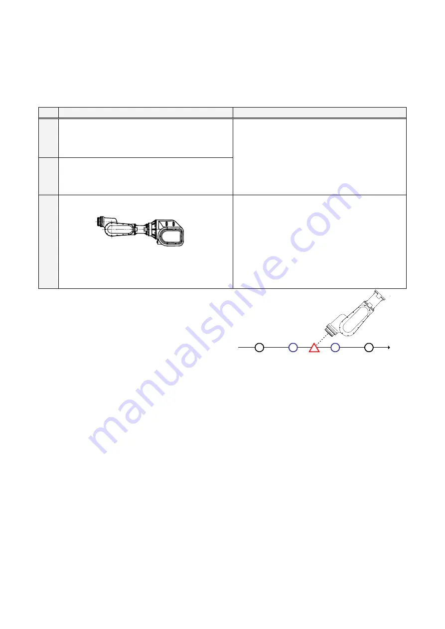
<Example>
The robot goes in an error condition at the point C
due to singular orientation of the robot when the
robot was moving from point A toward point B with
linear interpolation (see figure on the right).
Remedy:
Trace the robot backward toward the point A.
Add a teaching point of wrist calculation 0 (CL=0)
(
point D
).
Move the robot after the point of singular orientation
with Joint coordinates system.
Add a teaching point of wrist calculation 3 (CL=3)
(
Point E
).
Point
A
Point
D
Point
C
Point
E
Point
B
<Cautions>
•
The tool orientation may be unstable in the
CL=3 section (the wrist calculation is set to
3). Therefore, add another point before
the singular point (the point D) so as to
keep the CL=3 section (point D to point E)
as short as possible.
Ensure the robot operation at such section
by tracing at low speed.
•
If the CL=3 section is short but creates big
change of tool orientation, the robot travel
speed is reduced in order to ensure safe
operation.
•
To increase the robot travel speed, change
the interpolation of the teaching point from
linear to PTP and specify the speed you
want in %.