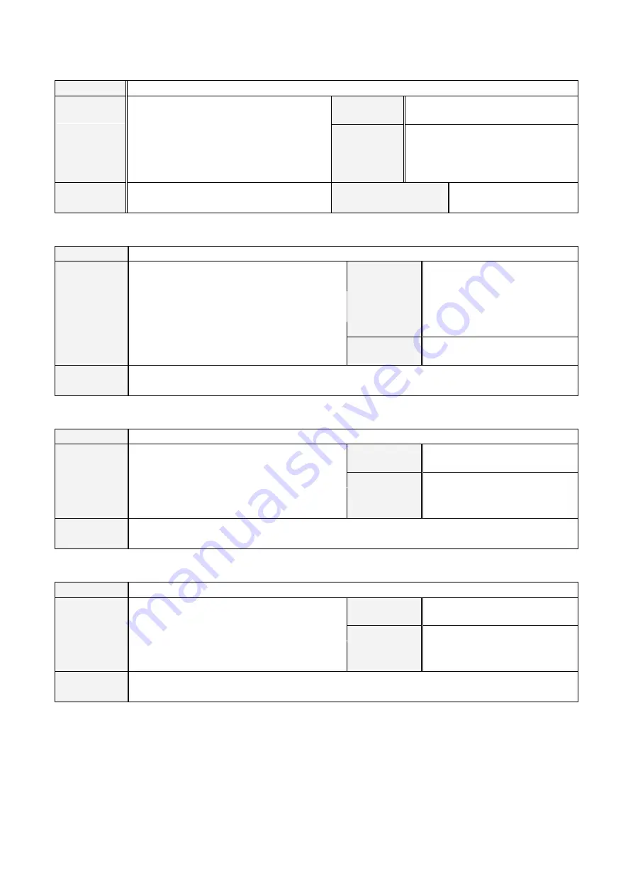
Panasonic VR2 Series Operating Instructions Manual Download Page 168


16-12

16-4-13.  SET 

Format 

SET [Variable 1] [Variable 2] 

Function 

It assigns a real number or variable to another 
variable. 

Variable 1 

Target variable 
(GB,LB,GI,LI,GL,LL,GR,LR,GD,GT) 

Condition 

Standard. 

Variable 2 

Lock 
condition 

None. 


Assigned value or variable (of the 
same type). 

Syntax check 

None. 


Example 

Set 10 to variable LR001 

SET LR001 = 10


The same command in 
conventional models 

SETREG 


16-4-14.  SETEL 

Format 

SETEL [Variable] = [Data] 

Function 

It assigns a value to a constituent of the variable

Variable 

Target variable 

Element (GD, GT) 

Condition 

None. 

Lock condition 

None. 


X: a point on the X-axis. 
Y: a point on the Y-axis. 
Z: a point on the Z-axis. 

Syntax check 

Error if variable to be assigned to is not teaching 
point type, 3-D type or robot type variable. 

Data 

Assignment value or Variable 
name (GR, LR, GD, GT) 

Example 

Set 100 to the element of variable GD001. 

SETEL    GD.X GD001 = 100


16-4-15.  SIN 

Format 

SIN [Variable] [Data] 

Function 

It calculates a sine value and assigns the result 
to specified variable. 

Variable 

Variable the calculated value is to 
be assigned to. 

Condition 

Standard. 

Data 

Lock condition 

None. 


Syntax check 

None. 


Calculation or variable (of the 
same type) 

(Unit: degree) 

Example 

Calculate sin45 and assign the result to LR001. 

SIN  LR001  45


16-4-16.  SQRT 

Format 

SQRT [Variable 1] [Variable 2] 

Function 

It calculates a square root and assigns the result 
to specified variable. 

Variable 1 

Variable the calculated value is to 
be assigned to.    (GR, LR) 

Condition 

Standard. 

Variable 2 

Lock condition 

None. 


Calculation or variable (of the 
same type). 

Syntax check 

None. 


Example 

Calculate square root of 2 and then assign the result to LR001. 

SQRT  LR001  2


Summary of Contents for VR2 Series

Page 1: ...t tr ru uc ct ti io on ns s Standard controller type Built in welding machine type YA 1NA YA 1PA VR2 Series G2 GX Controllers Before operating this product please read the instructions carefully and save this manual for future use OM0105045E09 0105045 0403 ...

Page 2: ...harge of installation and or maintenance Robot controller Operating instructions The document explains transportation installation connection initial settings and maintenance and repair of the robot controller The contents of the document are limited to hardware of the equipment Note Initial settings of software at robot installation are shown in Operating instructions Advanced operation This docu...

Page 3: ...ual you have is applicable to the upgraded software version Note Higher version of software doesn t necessarily require revision of manual unless changes of software cause change in operation procedures Click the Version icon on the Help Help menu to check the software version Safety First of all please read and understand separately provided Safety Manual thoroughly for proper and safe operation ...

Page 4: ...this symbol it means that a hazardous accident including death or serious personal injury is imminent if directions are not followed carefully Warning When you see this symbol it means that the potential for a hazardous accident including death or serious personal injury is high if directions are not followed carefully Caution When you see this symbol it means that the potential for hazardous acci...

Page 5: ...or 4 19 4 14 Program test 4 20 4 14 1 Procedures 4 20 4 14 2 Override in the Program test 4 21 4 15 Advanced settings 4 22 4 15 1 Weld section shift 4 22 4 15 2 Wire touch detection in teach 4 23 4 15 3 Use of shift buffer data 4 23 4 15 4 Program Test 4 23 4 15 5 Trace settings 4 23 4 15 6 Weaving 4 24 4 15 7 R shift key and teach point settings 4 25 4 15 8 Auto edit of Arc start end commands 4 2...

Page 6: ...2 Customize function keys 12 1 12 2 1 User function keys 12 1 12 2 2 Robot move key 12 3 12 2 3 External axis key 12 3 12 3 Language settings 12 4 12 4 Screen saver settings 12 4 12 5 Programming Teach Folder settings 12 5 12 6 Favorite commands 12 6 13 System information Back up settings 13 1 Error Alarm history 13 1 13 2 Backup 13 1 14 Management tool settings 14 1 User management settings 14 1 ...

Page 7: ...IP 16 18 16 5 19 IP 16 18 16 5 20 I PFALL 16 18 16 5 21 I PRISE 16 18 16 5 22 ISC 16 19 16 5 23 ISL1 16 19 16 5 24 ISL2 16 20 16 5 25 PENET 16 20 16 5 26 PFALL 16 20 16 5 27 PFRQ 16 20 16 5 28 P HOTTM 16 21 16 5 29 PMODE 16 21 16 5 30 PPEAK 16 21 16 5 31 PRISE 16 21 16 5 32 STICKCHK 16 21 16 5 33 TORCHSW 16 22 16 5 34 TSO 16 22 16 5 35 TSP 16 22 16 5 36 VOLT 16 22 16 5 37 WAIT ARC 16 22 16 5 38 WF...

Page 8: ...TREV 16 44 16 15 4 VELREF 16 44 16 16 ARC ON ARC OFF sequences 16 45 16 16 1 CO2 MAG MIG welding 16 45 16 16 2 TIG welding 16 46 16 16 3 Powder plasma welding 16 46 17 Errors and Alarms 17 1 Alarm codes 17 1 17 2 Error codes 17 5 17 3 Welder error codes 17 11 17 4 Supplements 17 15 17 4 1 Remedy of E1050 17 15 17 4 2 E7XXX Load factor error 17 16 17 4 3 Lithium battery error 17 16 17 4 4 At power ...

Page 9: ...elding specification and Handling specification As for Advanced operation please refer to the latter part of this manual Contents 1 Structure 2 How to use the teach pendant 3 Get assistance while you work Help 4 TEACH mode 5 AUTO mode 6 Useful file edit functions 7 View ...

Page 10: ...s BW axis TW axis FA axis UA axis RT axis Operation box The robot in the above figure is VR 008 1 2 Teaching Playback Method The robot is a teaching playback robot A program of robot operation such as welding or sequential processing can be created by moving the robot arm This process known as Teaching can be stored in the controller By running the program the robot executes the series of taught o...

Page 11: ...ose which mode TEACH mode or AUTO mode you want to work with the robot The switch key is removeable 12 Function keys Each key is used to perform as per the function icon shown to the right of each function key 6 key This key is used to control continuous movement of the robot arm in the same manner as the Jog dial 7 Enter key This key is used to save or specify a teaching point or a choice in the ...

Page 12: ...em and save it 3 Jog drag Hold down and then jog up down To retain current operation of the robot arm The jog rotation amount of the dial after pressed determines the change value Stop the jog rotation to release Di rection of movement is the same as that for Jog up down The key works in the same manner as Jog drag 2 1 2 Window change key It switches between menu icon bar and edit window It switch...

Page 13: ...ion icons Auto Teach Window title bar Function keys 2 3 How to switch the external axes option There are two ways to switch functions of the motion function keys between main axes group and external axes Click External axis or Robot in the menu bar Hold down the L shift key to switch the displays of function keys FI FII and FIII from Robot main axes Wrist axes to External axes External axis 1 Exte...

Page 14: ...ange page Trace Trace OFF Weld No arc Interpolation change Coordinate system change Change page Arc lock Note Override Change page Operation Change page Window change Edit mode change Add command Change page Offline edit A file is open Window change Cut Copy Paste Change page Trace ON OFF Cursor UP Cursor DOWN Coordinate system change Change page Register teaching points robot or position variable...

Page 15: ...icons Jog up down to move the cursor red frame Click the jog dial to display sub menu items Click an icon to display sub menu items of the icon Move the cursor up to close the submenu Click the jog dial to close the sub menu Rest the cursor over the icon to display the icon name ...

Page 16: ...pen Program Recent files Copy Sub 2 Close Arc start program files Welding spec Paste Paste Paste Reverse Save Arc end program files Find Save as Replace Transfer Jump Properties Properties Rename Local variables Number adjustment Byte Integer Long Delete Protect Global variable settings Robot position Mechanism position Real number Option ...

Page 17: ...state Operation management Window Online Offline Arc weld information Current Voltage Weld input output Display Pulse condition Deviation count TIP CHANGE Monitoring feeder Add command IN OUT Flow Weld CO2 MAG Low pulse TIG Powder Calculation Numerical calc Logical calc Move Move command Move assist Shift Option Touch sensor External axis Harmonize Favorite ...

Page 18: ...output Controller Prog Start method User ID Resume Speed limit Motion parameter Disable program editing Advance setting TP Select coordinate system Key customize Another language Screen saver Folder settings Edit favorite commands System information Error history Alarm history Back up Save Load Verify Management tool User management Memory clear Controller Day Time TP Controller Origin position Sy...

Page 19: ...ular Speed High Delete Cylindrical Weaving User Circle weaving In Out Shift buffer Program Test MORE Help Teach settings Help Advanced settings Version Icons in AUTO mode Limit condition Program unit Cycle time Override Program change Offline programming Program unit Step unit Hot edit Welding data log Continuous Available only with built in welding power source type controllers ...

Page 20: ... keys To display upper case letters To display lower case letters To display numbers To display symbols Other keys to input characters Jog click To enter the selected character into the box Shift keys L R To move cursor left L and right R in the box Enter key To specify the entry Cancel key To cancel and close the dialog box Upper case Lower case Numbers Symbols Entry box Character 2 7 Memory chec...

Page 21: ...ey Page forward F4 key Page backward F5 key 1 Move the cursor over the Help menu and then click the Help icon to display Help window Move the cursor to the topic you want and then click the jog dial to get information 2 Press the Window change key to return to the robot operation window you were working on When the Window change key is pressed the Help window is closed retaining the current screen...

Page 22: ...e Cancel Closes this dialog box without saving any changes you have made Operation 1 Click the Set icon on the menu bar 2 Click the Controller icon 3 Click the Speed limit icon 4 The Speed limit dialog box shown next to the Î in the next line appears 5 Then complete the required settings such as selecting the prameters or entering values or chanracters in the box 6 and then click the OK button to ...

Page 23: ...ring system data When you turn ON the power source of the controller Make sure to allow at least 3 seconds of cooling time before turning ON the power again 4 3 User ID setting for the first time You must set the User ID to perform teaching or changing of robot settings It is so designed that with the User ID settings that originally came at shipment it is not possible to edit Click Set Controller...

Page 24: ...es the robot arm Robot motion OFF Moves the cursor Movement of the robot control point tool center point is displayed as a numerical value in the upper right corner of the window Releasing the Function key reset the value to 0 The joint coordinate system is set as default coordinate system unless otherwise specified To apply another coordinate system refer to section Switch the Coordinate system J...

Page 25: ...ordinate systems to choose from 2 Press the L Shift key to switch the coordinate system The Robot motion icon switches correspondingly 4 5 1 Robot motion icons and robot movement Robot motion coordinate system select menu Joint coordinate system Control the robot movement by axis individually Switch functions with L Shift key Joint Cartesian Tool Cylindrical ...

Page 26: ... key Switch functions with L Shift key Direction of tool W H W For welding H For handling Tx Ty Tz W H W H W H W For welding H For handling Cylindrical coordinate system Controls the robot movement based on the cylindrical coordinate system User coordinate system Controls the robot movement based on the coordinate system specified by the user X Y Z Xu Yu Zu Switch functions with L Shift key Switch...

Page 27: ...and data for robot travel method from the teaching point to the next teaching point with or without welding Interpolation PTP MOVEP Joint movement Linear MOVEL The robot follows a straight path from a point to the next Circular MOVEC The robot follows a circular path determined by three teaching points Weaving MOVELW The robot follows a zigzag course on a straight path Data to be stored Position o...

Page 28: ...Turn ON the Robot motion ON icon lamp so as to move the robot manually 2 Bring the edit window to an active state 3 Move the robot to the start point and then press the Enter key The dialog box below appears 4 Change fields in the box if necessary and press the Enter key or click the OK button to save it as the teaching point Teaching point Travel method Interpolation speed etc All of this informa...

Page 29: ... certain position can result in what is called singular orientation of the robot which can cause flip over of the axes In order to avoid possible flip over of the axes specify a calculation type of interpolation the CL number CL No Calculation application 0 Automatic calculation 1 Suitable in circular interpolation if the arc plane and the tool vector create nearly at right angles tolerance within...

Page 30: ...as a circular start point 1 Move the robot to an intermediate point of the circular path you want to create and press the Enter key 2 Then the dialog box to set teaching point appears Press the Enter key if change of parameters is not necessary The point will be saved as a circular intermediate point 1 Move the robot to the point you want to end the circular line Press the Enter key 2 Then the dia...

Page 31: ... c to calculate interpolation Linear interpolation Use points b c and d to calculate interpolation Use points c d and e to calculate interpolation Use points c d and e to calculate interpolation Supplement 1 Linear interpolation is applied to the circular start point 2 To create a locus of a combination of more than one circular pattern save a Linear interpolation point or PTP interpolation point ...

Page 32: ...ntermediate point s Teaching of a welding end point 1 Move the robot to the point to you want to start welding and press the Enter key Then the dialog box to set teaching point appears 2 Change the attribute in the dialog box to Weld 3 Press the Enter key to save the point as a welding start point 1 Move the robot to a point within the welding section and press the Enter key Then the dialog box to...

Page 33: ...stored in the CRATER command when saving the arc end point ARC OFF file name Specifies the default file name to be stored in the ARC OFF command when saving the arc end point Stick release No Specifies a stick release table number Set range table 1 5 Note Note As for built in welding power source controller the table 6 and 7 are available which is to retract wire automatically when the stick relea...

Page 34: ...ove the robot to the other point to determine the weaving amplitude Amplitude point 2 Then save it as Amplitude point 2 in the same manner of Amplitude point 1 2 As for weaving pattern 4 or 5 teach two more amplitude points 3 and 4 in the same manner 1 Move the robot to the point you want to end weaving and then press the Enter key The dialog box to set the teaching point appears 2 Set parameters ...

Page 35: ...rection of the main trace on the weaving end point Weaving timer It determines how much time in seconds the robot waits before traveling to the other amplitude point During the period specified by the timer the robot travels forward in the direction of the main trace 2 1 S Timer 1 Timer 2 Main trace Conditions For patterns 1 to 5 Amplitude Frequency must not exceed 60 mm Hz For pattern 6 Angle of ...

Page 36: ...2 Circular weaving intermediate point MOVECW intermediate Amplitude point 1 WEAVEP Amplitude point 2 WEAVEP Linear Circular weaving start point Circular weaving end point Interpolation MOVECW start MOVECW Circular weaving intermediate point Circular weaving end point 1 Move the robot to a point on and within the circular weaving path you want 2 Press the Enter key The dialog box to set teaching po...

Page 37: ...ection of the is not matched with the the robot cannot move Ex against 4 11 2 Add teaching points Turn ON the Robot motion ON icon lamp and move the robot to the new location you want to add as a teaching point and then save it Click Edit type Add You will find the edit type icon used in the preceding edit operation in the menu bar 1 Bring the edit window to an active state 2 Press the Enter key T...

Page 38: ...ing point to the current teaching point Wrist calculation Normally set 0 Or specify 1 2 or 3 for special calculation The field is not available if the teaching point is MOVEP 4 11 4 Delete teaching points In trace operation move the robot to the taught point you want to delete The cursor moves to the same point in the screen Click Edit type Delete You will find the edit type icon used in the prece...

Page 39: ... Trace forward Trace backward Original robot motion 4 5 3 4 5 3 4 5 3 Manually move the robot 4 5 3 Moves the robot manually 4 5 3 4 5 3 Add a point 4 5 3 6 New point Add the teaching point 6 6 4 3 5 4 6 3 5 Change position of a point 4 5 3 New position Change the teaching point 4 4 5 3 4 5 3 Delete a point 4 5 3 Delete the teaching point 4 5 3 5 3 indicates location of the robot control point aft...

Page 40: ...oint after exit or trace forward backward 4 13 I O monitor It displays user input output state when the robot is in the hold state It is possible to change ON OFF state of outputs with this display This I O monitor function is available when the mode select switch is in the TEACH position 1 Place the mode select switch in the Teach position 2 Turn ON the In Out icon on the menu bar to display the ...

Page 41: ...ation will go into the AUTO mode with same robot arm position Even if the Mode switch is changed to AUTO from PROGRAM TEST and is returned to TEACH again the operation is not returned to PROGRAM TEST It will go normal TEACH mode 4 14 1 Procedures Turn on Program Test icon to operate the Program Tset The Progra Test is operated with Function keys and the User function keys in the Teach box Fuction ...

Page 42: ...tput Output after executing GOHOME command Override X Home return status output X Back up X O Avaiable X Not available 4 14 2 Override in the Program test Change Override of Program test in the advanced setting to Valid before operation Press the F1 key Override icon to turn on the Override in the Program test The lamp is lit and the function keys are changed to icons for override operations Note ...

Page 43: ...otion and actual welding under the safety condition in TEACH mode Trace settings A function that enables trace operation at the speed other than teaching speed Weaving A function that enables to specify weaving settings for each teaching point individually R shift key and teach point settings It specifies how the confirmation dialog box is to be displayed at teach point settings Î Auto edit of arc...

Page 44: ...rk is detected The red light is lit unless corrected 4 15 3 Use of shift buffer data Valid Invalid Specifies the validity of the function It is factory set to Invalid at shipment Select Valid to add Wire touch icon on the menu bar ON Green lamp is ON Trace operation using shift buffer data OFF Light is OFF Trace operation of teaching points 4 15 4 Program Test Method Single hand Single hand operat...

Page 45: ...e as they are special weaving patterns As for weaving patterns 11 to 15 the Weaving direction is automatically set to Reference to amplitude points as the robot movements of those patterns are based on the external axis Movements of Direction of weaving amplitude Simple weaving Reference to amplitude points S E B2 B1 S E B2 B1 Movements of Change direction of weaving amplitude Change at teach poin...

Page 46: ...er keys to add Whether to display the confirmation dialog box when both Enter and R Shift keys are pressed Change item s when Whether to change the menu data when to change a teaching point without displaying the dialog box Change only point data Change both point data and menu data which includes Interpolation type speed and so on 4 15 8 Auto edit of Arc start end commands Display the confirmatio...

Page 47: ... a list of arc end program files Welding spec Jog the dial over the files and select the file you want to open Then click the jog dial to open the file Î Name Specify the name of file to open User Indicates user name of the specified file Comment Indicates comments of the specified file Type Program Arc start Arc end Symbols indicate those files are protected Please refer to section File protect f...

Page 48: ...he line of the sequence command you want to change Click Edit type Change You will find the edit type icon used in the preceding edit operation in the menu bar The Command list same as the above appears Set the parameters and then click the OK button When you change CALL or PARACALL command Click a CALL or PARACALL command you want to change to display the program to be called by the argument Then...

Page 49: ... point Change to Air cut point Sequence commands frequently used in welding operation Command Definition How to set ARC ON Specifies welding start conditions Select one from welding start programs ArcStart1 to ArcStart5 torch switch ON welding current detect etc ARC OFF Note Specifies welding end conditions Select one from welding end programs ArcEnd1 to ArcEnd5 torch switch ON Wire stick detect e...

Page 50: ...rams Arc ON program ArcStart1 to ArcStart5 Arc OFF program ArcEnd1 to ArcEnd5 4 16 7 File sort Files in the displayed file list by File open operation or so on can be sorted in the following orders Sort key Sorting order Name A to Z Alphabetical order of file name from A to Z Name Z to A Alphabetical order of file name from Z to A Time New to Old In order of time from latest to old Time Old to New...

Page 51: ... you closed the file without saving the data you loose all teaching data or the changes you have Save Overwrites data Save as Names the active file and save it Click File Save Save as Save Î 4 18 Close a file When you are finished teaching or editing points you close the file Click File Close ...

Page 52: ...ition Close any active program file s first Click File Transfer Î Select and click the folder where the file you would like to transfer is stored Then a list of files in the specified folder appears in the right window pane Press the Window change key to bring the right window to an active state Click the file s to transfer from the list You can select more than one file The selected files are mar...

Page 53: ...m size File size Creator User ID User ID who created the program Created Date when the file was first saved Modified Data when the file was saved last Original program The original file name if the file was save using Save as or was renamed Program edit Current file protect state Protected Current protect level OK Click to update the Command and or Mechanism 4 20 2 Rename a file You can change the...

Page 54: ...ow Point Change Only It allows to change position of teaching points but not possible to change any commands None The file is fully editable No protection 2 Setting procedure using Properties dialog box Protected Protect level Display Depending on the protect level a symbol is added to before the file name of each protected file on the file list screen Symbol Description x Protect All Allow Point ...

Page 55: ...le to undo once deleted Click File Delete Î 1 Cick Controller in the System window to show the file list 2 Change the window and select the files you want to delete in the file list A seleced file attaches a mark 3 Press Next F3 button to show the file list to delete 4 Press Yes to delete Î ...

Page 56: ...Emergency stop button at any time the operator observes danger 1 Position yourself outside of the safety fenced area and lock the door of the safety fence 2 Place the mode select switch to the Auto position 3 If the robot is provided with the operation box press the AUTO switch to bring the robot in AUTO mode The operation box is optional for some robot models To ensure safe operation the operatio...

Page 57: ...tart Warning Bring the robot to an emergency stop immediately when you observe hazardous or an abnormal condition Make sure that no personnel or any articles to interfere with the robot are present within the robot work envelope prior to restarting the robot 1 Press the Emergency stop switch to bring the robot to an emergency stop 2 Remove the cause and then turn on the servo ON and then start swi...

Page 58: ...ous Performs a preset series of programs and then stops Click Program unit 5 6 Cycle time It is to set program s to indicate individual cycle time Click Cycle time Î Click on the Browse button to select a program from a list of registered programs Unless a program is specified asterisks appear to the next to the check box To display the cycle time Click View Operation management ...

Page 59: ...t use this function Click Override ON Turn off the override icon to end the adjustment Both hands Default setting at exfactory Single hand Setting change required While holding down the function key jog the jog dial to adjust the setting and click to update Check the adjusting table number which is set adjusting data L shift key of the Teach pendant changes the override objects Enhanced display sh...

Page 60: ...tion of offline edit close the file Turn OFF the Offline programming icon lamp Each time you press the I key the function changes from Add Change Delete 5 9 2 Program change in parallel processing In AUTO mode when two programs are executed at a time using PARACALL command etc it is possible to switch the programs displayed in the window The program displayed in the window is the object program of...

Page 61: ... to save the data on the StorageMemory card Data will be stored in the CSV format as follows using the start date of recording as the file name It is easy to make a graph of the data using a spreadsheet software Format WLY Y M M D D h h m m txt File name Y Y Year the last 2 digit of calender year M M Month D D Date h h hour m m minute Example WL0303071436 txt Example Format 03 03 07 14 36 120 18 4...

Page 62: ...racter string data to be used when moving or copying the data If you want to insert the data you have just cut to a different place or file do Paste The character string data in the clipboard will be stored until execution of the next Cut operation 6 2 Copy It stores data of the selected line s in the clipboard 1 Move the cursor to the line you want to copy 2 Use the jog dial to select highlight t...

Page 63: ...ul to edit data for reciprocating motion Teach the first half of the motion and copy it and then do Paste Reverse to complete the latter half of the motion Pasting the data stored in the clipboard once does not delete the data from the clipboard You can Paste the data as many times as you want 6 4 Find Find the command in the file that satisfies the condition you specified Click Edit Find Î Browse...

Page 64: ... searches for the next instance of the label or teaching point name you specified and jumps the cursor to the location if found Click Edit Jump Î Type the text you want to jump to Label Finds a label in the program Teach pt Finds a teach point in the program Partial match Check the check box to find data that has partially matches the text you specified Next Search forward from the cursor position...

Page 65: ...value of a local variable It also can increase the number of local variables to be registered Click Edit Local variables Î Select a variable type you want to edit Examples Number adjustment Î Enter a number of local variable to be registered in the box of the variable type you want to change Set range 5 100 Byte Î ...

Page 66: ...alid variable the following dialog box appears Apply To change data Invalid To invalidate the data Cancel To cancel the action and close the dialog box How to check the setting You can check the settings by moving the robot to the registered position in trace operation 1 Move the cursor to the number 2 Turn ON the trace icon lamp and jog the jog dial while holding down the Function key Then the ro...

Page 67: ...allel shift External axis shift Conversion Specified conversion type Program for conversion Program to work on Save program name Specifies the file the converted program is saved to Change the file name if you want to save the converted program in a different file Shift data Specifies the shift amount Conversion section Specifies the section to be converted Calc error Specifies a process to be app...

Page 68: ... variable robot variable method 1 With the teaching point method Open the program you would like to use to set tool compensation With the robot variable method Close all active programs to start settings 2 Click Edit Option Î Select the Compensation of tool and then click the OK button 3 Click the OK button Move the cursor to the taught point or to the variable in case of robot variable method is ...

Page 69: ...set dialog box indicates that the tool has applied the tool compensation 6 9 3 Global variable setting for TCP adjustment TCP Tool center point It is a setting to assign tool position data to global variable in order to calculate tool offset value Please refer to section TCP tool center point adjust in Advanced operation for further information ...

Page 70: ...ick View File list Î 7 2 Display change 7 2 1 Position display It displays the current position of the robot control point in angles of axes or pulse counts Click View Display change Display position XYZ Angle Pulse XYZ Î XYZ Robot control point data on the robot coordinate system UVW Tool orientation U Angle rotating around the axis parallel to Z axis including the robot control point while retai...

Page 71: ...ge Display I O terminal Î Terminals in ON state are indicated in green Terminals in OFF state are in gray 7 2 4 Status IN OUT It displays ON OFF state of each status I O port Click View Display change Display status IN OUT Î Terminals in ON state are indicated in green Terminals in OFF state are in gray 7 2 5 Variable It displays values saved in global variable Click View Display change Display va...

Page 72: ... executed Peak load factor The maximum load factor of each axis of the program executed When Load factor is selected Î Load factor for each axis is displayed to the right of the colon Note For handling robot make sure to position each axis so that its load factor does not exceeds 100 7 2 8 Accumulated time It displays accumulated times Click View Display change Accumulate time Î Controller ON time...

Page 73: ... Reserve state 7 3 Operation management This function is to calculate and display a program running time Click View Operation management Î Program name Running time of each program Total running time Arc ON time of each program Running time Time from startto stop of a program is counted When Re set operation is executed after a program is stopped with hold emergency stop or error stop the running ...

Page 74: ... top of the screen and bring the program to an active state Online Specify a program from programs currently in operation teaching or edit operation Offline Specify a program from OFFLINE editing programs Click View Window Î OK To display the specified file on top ...

Page 75: ...welding status Click View Display change Monitoring feeder Icon Screen display Current Voltage Weld input output Deviation count TIP CHANGE Monitoring feeder If a digital controlled wire feeder is applied it is possible monitor status of the wire feed motor ...

Page 76: ...nts 8 Variable settings 9 Input Output settings 10 Robot settings 11 Controller settings 12 Teach pendant TP settings 13 System information Back up setting 14 Management tool settings 15 Arc welding machine settings 16 Commands 17 Errors and Alarms 18 Appendix ...

Page 77: ... Identifier B Byte I Integer L Long integer R Real number P Position D 3 Demensional T Rotary Shift A Robot Default Auto name is 3 digit number G Global variable name Global variable names including the identifier can be changed to any 8 alphanumeric character name Identifier Variable type Definition B Byte 1 byte integer Set range from 0 to 255 If the variable represents ON or OFF assign 0 for OF...

Page 78: ...rotary shift conversion amount is to be assigned to 20 Click A desired variable button Robot Sets robot variable 100 Position Sets teaching point variable 100 Î Variable name Displays the selected variable name Comment Provides a space for you to add comment about the variable Comments can have up to 20 characters Current value Displays the current set value of the selected global variable Rotary ...

Page 79: ...128s are ignored or treated as OFF As for input 16s to 128s are treated as OFF Ignored 4 bit group input D03 D02 D01 D00 Output value 128 64 32 16 8 4 2 1 Example 1 0 OFF OFF OFF OFF OFF OFF OFF OFF Example 2 1 OFF OFF OFF OFF OFF OFF OFF ON Example 3 21 OFF OFF OFF ON OFF ON OFF ON Example 4 106 OFF ON ON OFF ON OFF ON OFF Example 5 255 ON ON ON ON ON ON ON ON 2 Logic operation It is possible to ...

Page 80: ... point registration Click Browse in the Add dialog box to select P1 from the list MOVEL P1 7 5 m min MOVEL P2 7 5 m min MOVEL P3 7 5 m min MOVEL P1 7 5 m min Then P1 is added below P3 or Copy the P1 MOVEL P1 7 5 m min MOVEL P2 7 5 m min MOVEL P3 7 5 m min Copy the whole P1 commands Move the cursor to the P3 line and then do paste MOVEL P1 7 5 m min MOVEL P2 7 5 m min MOVEL P3 7 5 m min MOVEL P4 7 ...

Page 81: ...ER 3D It executes the 3D transformation with reference to the user coordinate system Please note that if the ROBOT TOOL or USER Coordinate system is selected the rotary convertion after the parallel shift is executed on its axis However in case of the USER 3D the rotary conversion after the parallel shift is executed with reference to the shifted User coordinate system as the axis of rotation USER...

Page 82: ...Î USER IN 16 USER OUT 16 Sets 16 bit group input terminal In and output terminal Out 1 User input Î Select a name 1 bit input 4 bit input Terminal name Displays the selected terminal name Comment Provides a space for you to add comment about the terminal Comments can have up to 20 characters Usage Displays the function allocated to the terminal Signal logic Specifies whether the signal should be p...

Page 83: ... signal to run a program In a hold state turn on to restart The input signal is ignored under the following conditions The servo power is OFF Auto operation is not set In error condition Stop input is ON In override state Stop input Turn ON this input signal to bring the operating robot into a hold state While the signal is ON re start manual operation and trace operation are not operable The robo...

Page 84: ...y output The signal is output when the robot is ready to receive a status input signal It goes OFF when the robot is in an alarm condition or when the Emergency stop input is ON Servo ON output The signal is output when the servo power is ON Running output The signa is output while running a program including override It is turned OFF when the robot goes in hold or emergency stop state and turned ...

Page 85: ...o indicate completion of preset procedure after the initial servo ON when the main power 200 V is turned ON The preset is executed only after the initial servo power ON The setting is applied the next time you turn ON the power Weld off Valid Invalid Specifies the validity of the function Input terminal Specifies the input terminal name to be allocated to the user input terminal Output terminal Sp...

Page 86: ...epted when all files are closed after completion of operation This input is accepted while a file is open in offline edit operation The input is ignored when the Override is in the ON state or while setting a dedicated output such as an allocated output for Cube monitor To reset the output in teach mode click the reset icon on the Display I O terminal box Reset icon Home return output Valid Invali...

Page 87: ...al re start input Valid Invalid Specifies the validity of the function Input terminal Specifies the input terminal name to be allocated to the user input terminal It is an input that limits the re start input after the robot goes in the hold state effective only from a specified external re start input When this Ext re start input is set effective the Start input of the Status input cannot be used...

Page 88: ...equires immediate response Click Set IN OUT Hi Speed In Hi Speed In Sets one bit input terminal In and output terminal Out Î Î Select a number U24V M STATUS IN 1 8 STATUS OUT 1 8 EXIN1 2 IN 1 8 OUT 1 8 IN 9 40 EXOUT1 2 1B 1A Terminals are labeled EXIN1 2 and located between status output terminals and user input terminals 9 40 OUT on the sequence board ZUEP5711 Set parameters and click the OK butt...

Page 89: ... 1 2 Setting procedure Click Set Robot User coordinate Î Valid Invalid Specifies the validity of the function P1 Specifies the origin of the user coordinate system P2 Specifies a point to define the direction of X axis from the origin P1 P3 Together with the P2 specifies the X Y plane Browse Click the check box of P1 P2 or P3 and then click this button to select a set of X Y and Z values from the ...

Page 90: ...ovement when using malfunction in the tool coordinate system in manual operation The robot can handle up to 30 tool offset values and switch between them as needed during operation 10 2 2 Definition of XYZ type tool offset It uses 6 parameters X Y Z Tx Ty and Tz to determine the tool offset The position of the control point is determined by the parameters of X Y and Z and is indicated by the flang...

Page 91: ...h parameter refer to manual of applied equipment TW Plane of L1 L2 and L3 Plane Q TW rotation center Flange surface L2 L1 L3 Point P Control point L2 10 2 4 Setting procedure Set the control point of the manipulator on which an interpolation movement of the robot is controlled to be operated Click Set Robot Tool Welding robots Î Handling robots Î Tool name Type the tool name the identifier of each...

Page 92: ...ied monitoring area The robot stops at the boundary of the specified monitoring area when an external signal is input Use this function 1 When multiple robots are used and interference may be the case depending on the direction of those robots Use this function to avoid collision 2 In a system where a conveyer is located close to the robot with this function you can stop or reduce the speed of the...

Page 93: ...ot is within the specified monitoring area Rectangular solid area is specified as a monitoring area therefore it is called Cube monitor By monitoring the movement of the tool center point the tip position of the tool with this function it is possible to prevent interference collision of robots if more than one robot is used in the same work area The functions of Cube monitor 1 It outputs signal wh...

Page 94: ...axis is positioned within a specified area Like RT monitor and Cube monitor it is possible to bring the robot to an error stop before the external axis enters the specified area Note This function is available to a person with the programmer or higher level Click Set Robot Area monitor Ext Axis range monitor Valid Invalid Whether to enable this setting Ext Axis The axis to be monitored Range A ran...

Page 95: ...robot into an error stop when all conditions are satisfied Note This function is available to a person with the programmer or higher level Click Set Robot Area monitor AND condition monitor Select a number Valid Invalid Whether to enable this setting AND condition Specify Type of area monitor Area number and ON OFF Within Out of the area Auto re start Click in the box to restart operation automati...

Page 96: ...es the operating range of the BW axis TW Specifies the operating range of the TW axis Default Resets the settings in this dialog box to the factory settings at shipment 10 7 Jog settings Jog is a type of operation to move the robot a little at a time The Jog settings is to set the robot travel amount corresponding to the jog dial increment Click Set Robot Jog Welding robots Î Handling robots Î Car...

Page 97: ...nt jig used for the first position and the TW rotation center match Teach 3 positions on X Z plane of the tool Teach 3 positions on X Y plane of the tool 10 8 2 Adjustment 1 TCP data setting 1 Close all active programs to start adjustment 2 Click Edit Option Î Select the Global variable for Adjustment of TCP 3 Specify a tool you would like to adjust 4 Then a list of robot variables appears 5 Posit...

Page 98: ... the ENTER key 8 Rotate the Y axis again to change the position for the third position on the tool X Z plane Position 3 9 As for Positions 4 to 6 teach position on the tool X Y plane For Positions 5 and 6 only Z axis of the tool coordinate system is operable 10 Click File Close to close the list of the robot variables Then a dialog box to confirm updating the adjustment appears Click the OK button...

Page 99: ... 16 32 64 128 256 and 512 Binary To start the program whose program number is equal to the sum of the numbers you specified It is possible to start programs of program numbers from 1 to 999 Auto Program select BCD A set of four terminals is used to specify each digit of the program number you want to start It is possible to start programs of program numbers from 1 to 399 Program name is indicated ...

Page 100: ...ut terminal to bring the master program in the ready state in case of forced termination of the master program Click the Browse button to refer to the list of input terminals The re open input executes the master program from the beginning It does not take it from the last operation Re call input accepts the OFF to ON change INPUT Allocation box Terminal layout of the sequencer card This User 24 V...

Page 101: ...l method When the start input is turned ON the same numbered program is selected Then the selected program will be executed With this method you can only program the program numbers 1 2 4 8 16 32 64 128 256 and 512 Timing chart Running output Program reserve XXX Reserved output XXX Start input Start operation About 0 5 s Program reserve YYY Reserved output YYY About 0 2 s About 0 5 s About 0 2 s P...

Page 102: ...0 5 s About 0 2 s About 0 5 s About 0 2 s Prog0ZZZ prg is selected Prog0YYY prg is selected XXX and YYY indicate program reserve numbers you specified 001 002 004 008 016 032 064 128 256 or 512 ZZZ is the sum of XXX and YYY The above example is of 2 program reserve inputs which are turned ON however ON OFF status of all program reserve inputs 001 002 004 008 016 032 064 128 256 and 512 are checked...

Page 103: ...ming chart Running output Program reserve XXX Reserved output XXX Output strobe Start input Program reserve YYY Reserved output YYY Input strobe Start operation 0 2 s or more 0 1 s or more About 0 5 s About 0 2 s About 0 5 s About 0 2 s Prog0ZZZ prg is selected Prog0YYY prg is selected XXX and YYY indicate program reserve numbers you specified 001 002 004 008 016 032 064 128 256 or 512 ZZZ is the ...

Page 104: ...nagement settings for details of the User ID Click Set Controller User ID Î Click the LOGIN icon Login Type a user ID that has been registered in the User ID box Or you can also click on the Browse button and select a User ID form the list robot The selected user ID will be displayed Type a user ID direct After operation is completed click the Logout icon to logout from the current user level and ...

Page 105: ...ming When the ready signal goes on at power ON the output signal turns ON simultaneously and stays on for about 3 seconds If conditions are specified input signal is accepted while the resume output is ON And once the input signal is accepted the output signal goes OFF Unconditional Conditional Ready output Resume output About 3 seconds Power ON Ready output Resume output About 3 seconds Power ON ...

Page 106: ...in Set the limit for override separately Set range 0 1 100 0 or 0 01 120 00 m min For handling robots This setting is not effective Limit speed set range varies with parts number of the robot controller and the robot manipulator 11 4 2 Joint speed limit It specifies the maximum travel speed for each joint axis Specify a percentage to the rated motor speed Click Set Controller Speed limit Joint Spe...

Page 107: ...orner 6 In the welding section in order to ensure smooth movement of the robot welding on the welding path the Smooth level automatically is set to 10 7 This smooth command has priority over the Smooth level settings That is although the smooth level is preset to 4 if there is a command SMOOTH 8 in a program the robot turns the corner at smooth level 8 MOVEL P2 SMOOTH 8 MOVEL P3 MOVEL P4 P3 P2 P4 ...

Page 108: ...in welding operation Errors this function corresponds This function corresponds to the errors listed in the following table Code No Description Code No Description W0010 No current W0150 Retry over W0020 No arc W0330 MIG TIG Force error W0025 No arc detected by robot W0340 MIG TIG Force count over W0030 Wire stick W0350 MIG TIG Force Wire buckling W0031 Stick check time out W0360 MIG TIG Force buf...

Page 109: ...ange 1 200 mm Input to escape Sets an input terminal User input No to execute the error handling function The robot starts the error handling function when the input terminal specified here is turned ON Completion output Sets an output terminal User input No to output the completion of retract movement the robot reaches the idle position And it goes off when the robot gets away from the idle posit...

Page 110: ... with the jig or the work along the retraction route first 1 Turn ON the preset user input Then the robot moves in the retraction direction When the robot reaches the idle position the preset user output is turned ON If the preset user output is 0 there will be no output 2 Remove the cause of the welding error 3 Press the START button to restart the operation The user output is turned OFF and the ...

Page 111: ... error handling function is available only when the robot operation is terminated by the welding error If the robot operation is terminated due to other reasons such as hold or an error other than welding error this function does not function even though the preset input is turned ON 4 If the error dialog box is closed this error handling function is deemed invalid Therefore even if the preset inp...

Page 112: ... processing conversion and data updating is carried out immediately 2 When setting the currently running program The shift processing conversion and data updating is executed when the robot reaches the first arc start point after the execution of Hot edit function For example if the first arc start point after the execution of the Hot edit function is P2 the robot stops at P2 for shift processing ...

Page 113: ...gram to be shifted The program to be selected can be either a running program or a stored one Select a weld line including points to be shifted Please note the following are not in the choice Weld line with a move command that uses global variables to specify its teach point Weld lines taught in the harmonic movement section It is possible to set only one weld line at a time Displays the previous ...

Page 114: ... arc start point and then start executing the shift process After the shift process is completed the screen on the right appears Yes Selects another weld line of the same program Then the dialog box shown in the previous procedure 3 appears No Ends the Hot edit function settings 11 8 4 Definition of shift coordinate system 1 Cartesian When Cartesian is selected teaching points are shifted along th...

Page 115: ...ser based on the applied work as per shown in the figure on the right With the user s coordinate system it is easy to identify the directions of X Y and Z as they are defined based on the work User s coordinate system Y direction X direction Z direction Relations with other functions Function Response of this Hot Edit function Arc retry If an arc start point is the designated point to be shifted t...

Page 116: ...con is OFF in TEACH mode Teach Select to customize User function keys to be used in teachings operation Robot motion icon is ON in TEACH mode Auto Select to customize User function keys to be used in AUTO operation P1 P5 Click the check box es to display the current User function keys of the selected page s Edit Click to display the dialog box to customize the User function keys of the page Click ...

Page 117: ...mmand Accumulate time Help Air cut Weld 4 Operate state Option Teach settings Sensor data 1 Find Help SHIFT ON data Replace Save Program files Jump Program files Recent files Save Recent files Close Program files XYZ Hot edit 5 Recent files Angle Close Display I O terminal XYZ Display status IN OUT Angle Select mechanism 2 Display I O terminal Harmo coordinate sys 3 Display status IN OUT Harmoniou...

Page 118: ... to Tool and that of the Tool coordinate system to Cartesian 12 2 3 External axis key It is a function that allows you to change the external axis key assignments to the keys This function is available when the external axis function is set Use page 3 onwards I II III 3 PAGE G1 G2 Applicable example In case of a system with two sets of twin axis positioner assign external axes of each set on one p...

Page 119: ...urning OFF the screen after a specified time duration of no operation Click Set Management tool Screen saver Î Shut off monitor time 10 120 Specify how much time between 10 to 120 minutes to wait for the next robot operation before automatically switching off the screen Select Invalid if you don t want the screen to be switched OFF Monitor on when error occur Click it to turn ON the screen when an...

Page 120: ...User function keys F1 to F3 To make a new folder under the selected folder To rename the selected folder To delete the select folder Î Press the Cancel key to end 2 To set default folder details Î Folder of teach program Specifies the folder to save the program in and also to open the program from Auto backup while editing Click to make a backup copy of the working program automatically at every s...

Page 121: ...ou want to add to the favorite command group and click the OK button Then the Edit favorite commands dialog box reappear with the command you have selected added in the list To delete a command from the group list Move the cursor to the command you want to delete and then click the Delete button How to use Click Add command Favorite Select a command you want to use and click the OK No command is r...

Page 122: ...lder Example of Error history screen Example of Alarm history screen 13 2 Backup It is recommended to make a backup copy of programs and settings saved in the controller You can rebuild memory from backup in case of a memory crash Click Set Back up Î When you make a backup data on a PC card insert the PC card with memory card embedded into the PC card slot at the near side of the TP Please refer t...

Page 123: ...copy will be made automatically at any time Load is available only by service engineers Loads a specified backup data to a specified file The dialog box to specify a file to a desired Save to file name similar to the one for Save appears Specify a file name and click OK Load Î After you specify a desired Save to file name and click the OK button Same name file Skip Skips the teach file if the file...

Page 124: ...system administrators Robot operation teaching and setting Attention Only users of the system administrator level can set change and delete all parameters You can add or delete a user and also change the level of a user User registration Registers and changes user s Auto login Display the login dialog box at power on Click Set Management tool User management Î Auto logout Monitors inactivity time ...

Page 125: ...ecific user ID Newly specifies a User ID Press the User ID settings button and then the Login box appears to specify a User ID 3 To set Auto logout Auto logout Î Time management of user ID Select Valid to display the User login screen automatically after the specified time duration of no operation Monitoring time in valid Specified how much time in minutes to monitor no operation state before disp...

Page 126: ...3 Date settings It sets date and time in the robot Click Set Management tool Day Time Î Errors Alarms etc use this setting when they are an event Please be sure to set up the appropriate time for your time zone ...

Page 127: ...s MDI Main axis Use encoder pulse to adjust the origin of the manipulator MDI G Use encoder pulse to adjust the origin of the external axis Teach Main axis Use teaching operation to adjust the origin of the manipulator Î Teach G Use teaching operation to adjust the origin of the external axis 14 4 1 Standard position Main or External axis Origin position Î Standard position G Î 14 4 2 MDI Main or ...

Page 128: ...ck box of the axis you would like to adjust and then click the Next button Move the manipulator or external axis to the origin with manual operation and press the Enter key to update the values Teach Main axis Î Teach G Î To end the settings Click File Close ...

Page 129: ... the applied robot installation type such as standard wall angle or ceiling and to adjust the XYZ direction of travel of the robot manipulator to match with the coordinate axes It is also possible to register the robot identification name System settings screen On the System settings screen select Edit under Robot and then click the OK button to display setting dialog box Î Type Specifies the appl...

Page 130: ...the Add option dialog box specify the External axis and click the OK button Check the external axis No added and then click the OK button 2 Set parameters System settings screen On the System settings screen click the External axis and Edit Î ID Specifies the external axis identification name Type Specifies the external axis type Base Axis The external axis on which this external axis is mounted S...

Page 131: ...e from the control of the program therefore it is possible to assign a different task to Mech2 Positioner 1 Mech 2 Positioner 2 Mech 1 It is also possible to operate multiple robots if they are connected as flexible multi cooperative robot and registered as one group mechanism The Mechanism number can extend up to 30 with System data Adjustment operation Robot Positioner 1 Positioner 2 File not op...

Page 132: ...manual of the adaptor unit 1 Add units On the Add option dialog box Specify either Expansion IN OUT or Analog I O you want to add and click the OK button 1 Setting ID number of Expansion IN OUT unit Î Enter the ID number of the last unit after new unit s has added Last ID number The ID number should start from 3 in ascending order by 1 that is if you add 3 units you should enter 5 Number of unit 1...

Page 133: ...you should enter 4 Number of unit 1 2 3 Î Last ID No of I O 3 4 5 2 To change Analog I O Enter the ID number of the last unit after the change Last I D number The ID number should start from 31 in descending order by 1 that is if you change to 2 units you should enter 30 Number of unit 1 2 Î Last ID No of I O 31 30 3 Remove all units System settings screen On the System settings screen click the D...

Page 134: ...ed in NEW or ROPERTY screen in FILE menu Click File New or Click File Properties NEW PROPERTY Note A welder is selected in the list of Welder set as default When Multi welder is not added in SYSTEM menu welding column is not displayed Example A system has a CO2 MAG welder and a TIG welder and the welding torch is automatically changed with a tool changer Program CO2_01 prg is set YD 350GB2 as weld...

Page 135: ... 7 Log file Log file of robot internal system is made The log file will be used for servicing purpose Click Set Management tool Log file Usual setting is Invalid 14 8 System data adjustment The Mechanism number can extend up to 30 if required It is possible to set up to 10 Cube monitor conditions Click Set Management tool System data adjustment Set parameters and click the OK ...

Page 136: ...ameters of built in welding power source up to 5 kinds Weaving settings Override Î No arc detection 2 Standard controller An initial screen for standard G2 controller is shown below Click Set Arc welding Configuration Weaving Override No arc detection Î Welder settings 15 1 Configuration settings It sets the environment of the connected arc welding machine in the robot You can specify up to five w...

Page 137: ...e Power adjustment is ranging between 0 to 15 VDC Current command and voltage commands for power adjustment share the same grand level Maximum output is 999 A or less and 99 9 V or less TIG welders Current and pulse frequency are adjustable within 24 VDC Maximum current is 999 A or less and maximum pulse frequency is 25 Hz or less How to create data for welder characteristics You can set a command...

Page 138: ...welder or Unlisted TIG for TIG welder Check the check box next to the Now set the parameter Example Unlisted MIG Parameters vary with selected welder type Out Char Î As the initial setting the only Make new characteristics is effective Click the OK button Set all parameters in the dialog box and then click the OK button Then a message to confirm the completion of calculation appears Click the OK b...

Page 139: ...ype a new name You can rename any defined welders freely 15 1 3 Delete a welder Î Select the welder you would like to change name or delete and click the OK button Click a welder name you want to change and then a message appears to confirm the deletion action 15 1 4 Set a welder as Default Î Check the box to the left of the welder you would like to normally use unless specified ...

Page 140: ...how long the robot to move parallel to the main trace at each amplitude point Unit second Then do the following settings Click MORE Teach settings Set a weaving pattern number to register and then click the OK button When a weaving point MOVELW is newly registered Value set in teaching Values set in the Weaving table Those preset parameters amplitude timer as Timer weaving FRQ as Frequency and wea...

Page 141: ...e override button Voltage Welding voltage increment or decrement per pressing the override button Speed Moving speed increment or decrement per pressing the override button 15 1 7 No arc detection No arc detection The robot is brought to an error stop when either the welding machine or the robot detects the No arc condition which means no current is detected during welding operation The detecting ...

Page 142: ... is to specify material of the wire and welding method to be applied in welding operation Settings must be performed for each welders if more than one welder are connected to the robot Wire Material Weld method Î Material Specify the material of the wire to be applied Wire Wire size diameter to be applied Method Welding method to be applied Motor Specifies reduction rate of the wire feed motor Tim...

Page 143: ...tput value That is when command TP says 200 amp and If welder says 199 amp then the current adjust value should be 1 200 199 If welder says 201 amp then the current adjust value should be 1 200 201 15 2 3 Wave adjust data It is for fine adjustment of each welding parameter on a global scale Wave adjust data Î Start End Parameters at arc start and arc end Arc wave Parameters of arc waveform Pulse s...

Page 144: ...justment value Set range 20 to 20 Increase the value to reduce chances of a wire stick as it extends the wire burning time Decrease the value to reduce chances of a burn back to the tip as it shortens the wire burning time Arc waveform Î ISL1 Specifies the short circuit current slope 1 Set range 7 to 7 ISL2 Specifies the short circuit current slope 2 Set range 7 to 7 ISC Specifies the short circui...

Page 145: ...to 7 PRISE Specifies the rise angle level of the pulse wave Set range 7 to 7 PFALL Specifies the fall angle level of the pulse wave Set range 7 to 7 Pulse slope Specifies switch for PRISE and PFALL parameters When the connected welder does not support this parameter set to Invalid Amperage Time PFRQ IP IB PFALL PRISE Penetration Î PENET Specifies the penetration control level based on straight pol...

Page 146: ...ster up to 50 sets of welding conditions in the table Table No 1 to 5 Appropriate set values for each welding method are automatically set Table No 6 to 50 Open to users settings ARC SET Specifies welding conditions at arc start CRATER Specifies welding conditions at crater welding i e at arc end 15 2 6 Inching speed It is to set the speed of wire inching when operated using the teach pendant Inch...

Page 147: ...matically uses to cut the wire at the arc end in case of a wire stick Stick release Î Re start Specifies whether to use this function Valid or not Invalid Current Specifies the wire fusing current Set range 1 to350 A Voltage Specifies the wire fusing voltage Set range 1 to 50V Weld time T1 Specify the wire fusing time Set range 0 0 to 9 9 s Wait un stick T2 Specifies how much time the robot will w...

Page 148: ...n tip replacement is needed Tip change Î The Reset IN No functions independently from tip change That is it resets the accumulated values whenever the specified input terminal is turned on regardless of tip change timing Tip change Specifies whether to use this function Valid or not Invalid Hold Specifies whether to hold the robot when the tip change warning appears Valid or not Invalid Arc time S...

Page 149: ...t before monitoring after the arc start Set range 0 5 5 0 OUT No Specifies the output terminal when the robot moves out of the monitoring range 15 2 13 Display weld condition It displays welding conditions amperage and voltage sent from the welding machine on the teach pendant Display weld condition Î Display weld Specifies how the welding conditions are to be displayed Range Specifies the scale r...

Page 150: ... signal Wire feed forward backward When the input is ON the robot feeds the wire forward or backward at low speed for the initial 3 seconds and then switches to high speed When the input goes OFF the robot stops feeding the wire Gas check Gas purge When the input is ON the gas valve opens When the input goes OFF the gas valve closes When the both the wire feed forward input and the wire feed backw...

Page 151: ...d welder to add another welder When you select this item you must specify the name of the welder you want to make a copy of Name of the backup Welder YC 300BZ1 YC 300BZ2 for DC TIG YC 300BP2 for AC DC MIX TIG 15 3 1 Welding mode The optimum welding mode is selectable from DC AC or mixed TIG and hard or soft pulse wave for YC 300BP2 model Welding mode 15 3 2 Weld condition It sets TIG welding condi...

Page 152: ...15 3 5 Pulse settings It specifies whether to apply pulse and pulse width to be applied Set pulse mode Î Pulse Specifies whether to use this function Valid or not Invalid Pulse width Pulse width in percentage 5 to 95 15 3 6 Wire control It specifies whether to use filler wire and conditions to be applied Wire control Î Filer wire Specifies whether to use the filer wire TIG I F board ID Specifies I...

Page 153: ...d Error Electrode contact Use the CHKVOLT command to change the benchmark voltage for determining the electrode contact Electrode contact Electrode contact detection Whether to use this function Voltage assumed contact Specifies the benchmark voltage for determining electrode contact Note This function is available to software version 3 00 or higher of the Welding machine YC 300BZ2 Turn ON the Vol...

Page 154: ...o make a copy of the currently defined welder to add another welder When you select this item you must specify the name of the welder you want to make a copy of Name of the backup Welder YP 200PB1 15 4 1 Weld conditions Powder plasma welding conditions are set Weld condition 15 4 2 Adjust value Difference between setting data and actual measured value are compensated Adjust value Current Compensat...

Page 155: ... 85 Upslope Upslope time 0 0 5 0 s Down slope Down slope time 0 0 5 0 s 15 4 5 Gas control Gas control PG preflow Pre flow time for Plasma gas 5 25 s PG postflow Post flow time for Plasma gas 10 30 s SG preflow Pre flow time for Shield gas 0 0 5 0 s SG postflow Post flow time for Shield0 gas 0 20 s 15 4 6 Inching speed Inching speed High High powder feed speed 0 100 Low Low powder feed speed 0 100...

Page 156: ...m to make a copy of the currently defined welder to add another welder When you select this item you must specify the name of the welder you want to make a copy of Name of the backup Welder Example Unlisted MIG Parameters vary with selected welder type Out Char Î Select Check characteristics The example shows changes in case that the actual output current is 182A when the set value is 180A Click t...

Page 157: ... Weaving amplitude Timer Weaving timer The same command in conventional models MOVECW Example Travel to the teaching point P5 with circular weaving interpolation at speed 7 5 m min using weaving pattern 1 whose amplitude is 0 5 MOVECW P5 7 5m min Ptn 1 F 0 5 If the next teaching point is MOVECW Pattern No specified here is applied to the movement toward the next teaching point If the preceding tea...

Page 158: ...ing point If the preceding teaching point is MOVELW Frequency specified here is applied to the movement toward this teaching point Timer is applied toward this teaching point 16 1 5 MOVEP Format MOVEP Position name Manual speed Function PTP interpolation Position name Teaching position type variable Lock condition Robot lock Manual speed The robot travel speed toward this point Syntax check None E...

Page 159: ... conventional models IN REG 16 2 2 OUT Format OUT Terminal type Terminal name Value Terminal type Output terminal type value or variable GB LB Function Digital output Output the signal to output port Condition Terminal types O4 O8 and O16 must be defined before to use O1 1 bit output O4 4 bit output O8 8 bit output O16 16 bit output Lock condition I O lock Output value ON or OFF or variable GB LB ...

Page 160: ...ion None Syntax check The specified call program doesn t exist Example Call the program named PROG001 prg CALL PRG001 prg The same command in conventional models GOSUB PROG 16 3 2 DELAY Format DELAY T Timer s Function Delay It stops operation of the mechanism for a specified period of time Timer Stop time Value GR LR Set range 0 00 99 99 Condition Standard Lock condition None Syntax check None Exa...

Page 161: ...sfied Execute 2 An instruction to be executed if the condition is not satisfied Example If the value of LB001 is 10 jump to Label LABL0001 IF LB001 10 THEN JUMP LABL0001 ELSE NOP The same command in conventional models IF 16 3 5 JUMP Format JUMP Label Function Move to a specified Label not necessary the next in sequence and execute operation Label Label name to jump to Character string Max 8 chara...

Page 162: ...cuted at a time in parallel For parallel execution of mechanisms it is necessary to add Multi mechanism function to the system of the management tool Execution errors In ON state Error stop in all cases The specified program does not exist More than 7 programs have been executed The specified program contains the same mechanism as the running program In OFF state The specified program has already ...

Page 163: ...nventional models RETPRG 16 3 12 RSV_CANCEL Format RSV_CANCEL Function Use it to clear all lists of the reserved programs Condition Standard Lock condition None Syntax check None Note The command is effective only when Program select in Auto start method is selected 16 3 13 RSV_PROG Format RSV_PROG program name Function Use it to add a program at the bottom of the reserved program list Program nam...

Page 164: ...e operation after 20 seconds of time WAIT_IP I1 001 ON T 20 The same command in conventional models WAIT IPORT T 16 3 16 WAIT_VAL Format WAIT_VAL Input No Condition Input value T Timer s Function Input No Variable GB LB GI LI It stops operation until the condition is satisfied If a time condition T is given it resumes operation after the specified time interval regardless of the result of the cond...

Page 165: ...4 3 CLEAR Format CLEAR Variable Parameter Function It clears the value of a variable name Condition Standard Variable Variable name or type whose value is to be reset to Zero Lock condition None Parameter Individual to specify a variable name to reset Syntax check None ALL to reset all variable values of the specified variable type The same command in conventional models RSTREG Example To clear th...

Page 166: ...ed as the value of the target variable name it omits decimals Condition Standard Variable whose value is to be referred to and the result is to be assigned to GB LB GI LI GL LL Lock condition None Variable 2 Syntax check Error if both variable 1 and 2 are teaching point type or 3 D type or if variable 1 and 2 are teaching point type and 3 D type Value or variable of the same type Example Divide va...

Page 167: ...pecified variable name after a division Variable Condition Standard Variable the remainder is to be assigned to GB LB GI LI GL LL Lock condition None Data Syntax check None Value or variable of the same type Example Calculate the remainder of LR002 LR003 and assign the result to LR002 MOD LR002 LR003 16 4 12 MUL Format MUL Variable 1 Variable 2 Function It multiplies values of a specified variable...

Page 168: ... 3 D type or robot type variable Data Assignment value or Variable name GR LR GD GT Example Set 100 to the element of variable GD001 SETEL GD X GD001 100 16 4 15 SIN Format SIN Variable Data Function It calculates a sine value and assigns the result to specified variable Variable Variable the calculated value is to be assigned to Condition Standard Data Lock condition None Syntax check None Calcul...

Page 169: ...ue is to be assigned to GB LB GI LI GL LL GR LR GD Syntax check Error if number of element of variable 1 and 2 do not match In case of combination of teaching point type 3 D type or robot type variable subtract only XYZ elements Variable 2 Numerical value or variable of the same type Example Subtract 10 from LR001 SUB LR001 10 Note If variable is applied to Variable 2 its variable type should be t...

Page 170: ...file Condition Weld package Lock condition Arc lock Internal execution Syntax check The specified file name does not exist Table Table number to execute automatic stick release 0 5 Input 0 for no stick release Note As for built in welding power source controller the table 6 and 7 are available which is to retract wire automatically when the stick release functions Example Execute ArcEnd1 file to e...

Page 171: ...ance range NEXT To the next step Syntax check Value T Time 0 01 999 99 s D Distance 0 01 999 99 mm NEXT No value Example ARCSLP AMP 180 VOLT 23 0 NEXT 16 5 7 BBKTIME Format BBKTIME Value Value Fine adjustment value which will be added to the system set value 20 20 Function It adjusts the burn back time Increase the value to extend the wire burning time which reduces chances of a wire stick Decreas...

Page 172: ...the gas valve Lock condition Arc lock Syntax check None Example Open the gas valve GASVALVE ON The same command in conventional models OUTB OPORT 210 16 5 11 HOTCUR Format HOTCUR Value Function It adjusts Hot current Value Adjustment value 3 3 Condition Lock condition Arc lock Syntax check None Example Set the Hot current to 1 HOTCUR 1 The same command in conventional models 16 5 12 HOTVLT Format ...

Page 173: ...els IB 16 5 15 IB2 Format IB2 Value Function It adjusts the secondary base amperage Value Adjustment value 50 50 Condition Lock condition Arc lock Internal execution Syntax check None Example Set the secondary base current to 1 IB2 1 The same command in conventional models 16 5 16 IF ARC Format IF ARC ON OFF THEN Execute 1 ELSE Execute 2 See application examples ON OFF Arc state ON Arc is ON OFF N...

Page 174: ...tion Weld package Lock condition Arc lock Internal execution Peak amperage Panasonic fully digital welding power sources 50 50 Other power sources 5 5 Syntax check None Example Adjust the system set value by 1 IP 1 The same command in conventional models IP 16 5 20 I PFALL Format I PFALL Value Function It adjust s gradient of falling pulse current Value Adjustment value 7 7 Condition Lock conditio...

Page 175: ...mmand in conventional models ISC Amperage Time Shorted Arc ISC ISL1 ISL2 IAC TSO 16 5 23 ISL1 Format ISL1 Value Value Function It adjusts short circuit amperage slope 1 of welding current waveform Increase the value to make the slope gentler Fine adjustment value which will be added to the system set value 7 7 Condition Weld package Lock condition Arc lock Internal execution Executing 1 adjustment...

Page 176: ... the system setting value Lock condition Arc lock Internal execution Syntax check None Executing 1 adjustment twice does not result in 2 Example Adjust the system set value by 1 PENET 1 The same command in conventional models PENET 16 5 26 PFALL Format PFALL Adjustment value Function It adjusts the pulse fall angle Value Condition Weld package Lock condition Arc lock Internal execution Syntax chec...

Page 177: ...djustment value 50 50 Condition Lock condition Arc lock Internal execution Syntax check None Example Adjust the pulse peak time to 1 PPEAK 1 The same command in conventional models 16 5 31 PRISE Format PRISE Adjustment value Function It adjusts the pulse rise angle Value Condition Weld package Lock condition Arc lock Internal execution Syntax check None Panasonic fully digital welding power source...

Page 178: ...ction It adjusts wire sticking prevention time Value Adjustment value 3 3 Condition Lock condition Arc lock Internal execution Syntax check None Example Adjust the wire sticking prevention time to 1 TSP 1 The same command in conventional models 16 5 36 VOLT Format VOLT Voltage Function It sets welding voltage Voltage Condition Weld package Welding voltage 0 1 99 9 V Lock condition Arc lock Interna...

Page 179: ...WD Format WIRERWD ON OFF Function It starts or terminates wire retraction ON OFF ON to start wire retraction Condition Weld package OFF to terminate wire retraction Lock condition Arc lock Syntax check None Prior to this command it is necessary to insert the AMP command that specifies wire speed Example Retracts wire WIRERWD ON The same command in conventional models OUTB OPORT 213 DELAY 0 1 OUTB ...

Page 180: ...ON section Check Check Check Check Check OFF section Check NO check NO check NO check NO check 16 5 43 WLDSPD Format WLDSPD Speed Function It specifies welding speed Speed Set value 0 01 120 00 m min Condition Weld package Lock condition None Also valid in the arc cut state Syntax check None Example Set the weld speed to 0 50 m min WLDSPD 0 50 The same command in conventional models Note It change...

Page 181: ...LPFRQ Format LPFRQ Frequency Function It sets low pulse frequency Frequency Low pulse frequency Condition 0 5 10 0 Hz Lock condition Arc lock Internal execution Syntax check None Example Set the low pulse frequency to 2 0 LPFRQ 2 0 The same command in conventional models 16 6 4 LPLEVEL Format LPLEVEL Value Function It sets the low pulse level Value Low pulse level 50 0 Condition Lock condition Arc...

Page 182: ...0 Hz Example Speed Welding speed 0 01 120 00 m min Set parameters for TIG welding operation whose base amperage is 120A peak amperage is 180 A filler speed is 10 frequency is 0 5 Hz and speed is 0 50 m min ARC SET_TIG Ib 120 Ip 180 WF 10 FRQ 0 5 S 0 50 The same command in conventional models AJO TIG 16 7 3 CHKVOLT Format CHKVOLT Detection voltage for electrode short Function It sets detection volt...

Page 183: ...ckage Base amperage Lock condition Arc lock Internal execution Syntax check None Example Set the base amperage to 100 A IB_TIG 100 The same command in conventional models IB 16 7 7 IP_TIG Format IP_TIG Peak amperage Function It sets peak amperage for TIG welding Amperage 0 to 999 A Condition Weld package Peak amperage Lock condition Arc lock Internal execution Syntax check None Example Set peak cu...

Page 184: ...odels PFRQ 16 7 12 TIGSLP Format TIGSLP Ib Base amp Ip Peak amp Slope range Value Function It slopes welding amperage Base amp Final slope base amp 1 999 A Condition Weld package Peak amp Final slope peak amp 1 999 A Lock condition Arc lock Internal execution Slope range Slope range definition T Time range D Distance range NEXT To the next step Syntax check None Value T Time 0 01 999 99 s D Distan...

Page 185: ...C DC or MIX Function It sets welding method and the AC TIG wave mode Wave mode Selection STD Hard or Soft Condition Lock condition Arc lock Internal execution Syntax check None Example Set to AC TIG welding with standard wave mode WMODE_TIG AC STD The same command in conventional models ...

Page 186: ... Internal execution Syntax check None Example Turn on the carrier gas CARRYGAS ON The same command in conventional models 16 8 3 CRATER_POWD Format CRATER_POWD Ib Base amp Ip Peak amp PF Powder FRQ Freq T Time Function It sets a crater filler welding condition Condition Base amp Welding amperage or base amperage at pulsed welding 5 200 A Lock condition Arc lock Internal execution Syntax check None...

Page 187: ...ls 16 8 7 PDUTY_POWD Format PDUTY_POWD Value Function It sets the pulse width Value Pulse width 15 85 Condition Lock condition Arc lock Internal execution Syntax check None Example Set the pulse width to 50 PDUTY_POWD 50 The same command in conventional models 16 8 8 PFRQ_POWD Format PFRQ_POWD Pulse frequency Function It sets pulse frequency Frequency Pulse frequency 0 5 25 0 Condition Lock condit...

Page 188: ... on or off the powder feed motor power ON OFF Powder feed motor control Condition Lock condition Arc lock Internal execution Syntax check None Example Turn on the powder feed motor PWDMOTOR ON The same command in conventional models 16 8 13 PWDSLP Format PWDSLP Ib Base amp Ip Peak amp Slope range Value Base amp End base amperage of the slope 5 200 A Function It sets a slope control condition for p...

Page 189: ...ck Internal execution Syntax check None Example Turn on the start gas STARTGAS ON The same command in conventional models 16 8 16 WAIT PLARC Format WAIT PLARC Function It waits pilot arc Non Condition Lock condition Arc lock Internal execution Syntax check None Example Wait by starting pilot arc WAITPLARC The same command in conventional models 16 8 17 WPLS_PWD Format WPLS_PWD ON OFF Function It t...

Page 190: ...p Peak WFS FRQ Frequency T Time Function It specifies crater conditions for TIG Force Base Amp Base amperage 1 999 A Condition Using TIG FORCE Peak Amp Peak amperage 1 999 A Lock condition Arc lock Internal execution Base WFS Min wire speed 0 10 30 00 m min Syntax check None Peak WFS Max wire speed 0 10 30 00 m min Frequency Frequency 0 0 500 0 Hz Time Crater time 0 00 99 99 s Example Perform crat...

Page 191: ...ution Syntax check None Stop Stop Forward on Start wire feed to forward direction Reverse on Start wire feed to reverse direction Preset FWD Start forward wire feed by preset amount with the WFLENGTH command Preset RVS Start reverse wire feed by preset amount with the WFLENGTH command Example WFEED Preset FWD Note Wire is fed with LOW speed when the feed speed is not specified 16 9 8 WFSLDN Format...

Page 192: ...ommand 16 9 11 WSPDSLP Format WSPDSLP WFSPEED Filler wire speed Slope range Value Function It slopes wire feed speed Final wire feed speed Condition Weld package Filler wire speed 0 10 30 00 m min Lock condition Arc lock Slope range Slope range definition T Time range D Distance range NEXT To the next step Syntax check None Value T Time 0 01 to 999 99s D Distance 0 01 to 999 99mm NEXT No value Exa...

Page 193: ...le Variable whose value is to be referred to and the calculated value is to be assigned to GB LB Syntax check Error if variable other than byte type variable is specified Data Value or variable GB LB Variable should be byte type Note As logical not is carried out for each bit NOT 0 11111111 255 A NOT A 0 1 Example Store the result of logical not of LB002 to LB001 NOT LB001 LB002 1 0 16 10 3 OR For...

Page 194: ...s out exclusive OR of each bit A B A XOR B 0 0 0 0 1 1 1 0 1 Example Store the result of exclusive OR of LB001 and LB002 to LB001 XOR LB001 LB002 1 1 0 16 11 Motion assist commands 16 11 1 GOHOME Format GOHOME Interpolation type Position name Speed Function It returns the robot to the home position Interpolation type An interpolation type to be applied when the robot travels to the home position C...

Page 195: ...dinate systems Variable Function It starts coordinate system shift Condition Standard Coordinate systems A coordinate system to be shifted Lock condition None Variable Shift amount GD GT Syntax check None Example Shift the operation onwards on the robot coordinate system by GD001 SHIFT ON ROBOT GD001 16 13 Touch Sensor commands Optional 16 13 1 SNSSFTLD Format SNSSFTLD Variable Function It assigns...

Page 196: ...ne Syntax check None Example Reset sensor shift amount SNSSFTRST 16 13 5 SNSSFTSV Format SNSSFTSV Variable Function It stores the current sensor shift amount to the specified variable Variable Shift amount GD Condition Standard Lock condition None Syntax check Error if variable types do not match Example Store the sensor shift to GD001 SNSSFTSV GD001 The same command in conventional models RSTBUF ...

Page 197: ...P1 GD001 A variable name the value of which is assigned to the target point P GP GA GD Note To execute the rotary shift register reference points 1 to 3 and then execute the SNSSFT ON command The TRANSBASV command can be used together with the TRANSBASE command 16 14 Spin Arc Sensor commands Optional 16 14 1 SPNARC Format SPNARC Switch Function It starts or stop the spin arc sensor function Switch...

Page 198: ... frequency 5 REVDIR Revolving direction 12 STPPOS Revolution stop position Lock condition Arc lock Internal execution Parameter Syntax check None 1 MAXTRK 0 1000 mm 2 PHASE1 0 180 deg 3 PHASE2 0 180 deg 4 REVFRQ 0 50 Hz 5 REVDIR 0 AUTO 1 CW 2 CCW 12 STPPOS 1 AUTO 2 FRONT 3 REAR 4 LEFT 5 RIGHT Example Change the max tracking distance to 100mm SPNPRM 1 MAXTRK 100 0 The same command in conventional m...

Page 199: ...ormat EAXS_SFT OFF Ext Axis See application examples Function It terminates the external axis shift EAXS_SFT command Ext Axis Condition Lock condition None Syntax check None The external axis number the applied EAXS_SFT processing to be terminated G1 G21 including ones for slave robot Example Terminate the shift of the external axis G1 EAXS_SFT OFF G1 The same command in conventional models Note T...

Page 200: ... RSTREV Note If the specified external axis is not rotary type the command is ignored 16 15 4 VELREF Format VELREF Speed reference Function It calculates speed according to the specified mechanism Speed reference Condition Standard Lock condition None Syntax check None Robot axis Motion speed is calculated based on the robot movement External axis Motion speed is calculated based on the movement o...

Page 201: ...FF DELAY 0 30 DELAY 0 30 DELAY 0 30 DELAY 0 10 6 GASVALVE OFF STICKCHK OFF STICKCHK OFF STICKCHK OFF WIRERWD OFF 7 GASVALVE OFF GASVALVE OFF GASVALVE OFF STICKCHK ON 8 DELAY 0 30 9 STICKCHK OFF 10 GASVALVE OFF 11 Welding end programs factory set at shipment GX Controller ArcEnd1 ArcEnd2 ArcEnd3 ArcEnd4 ArcEnd5 1 TORCHSW OFF DELAY 0 10 DELAY 0 20 DELAY 0 30 TORCHSW OFF 2 STICKCHK ON TORCHSW OFF TOR...

Page 202: ...0s 5 DELAY 2 00s STICKCHK ON 6 OUT o1 XXX ON DELAY 1 00s Terminal No XXX represents the terminal that has been connected to the wire feed terminal of the filler wire controller 7 STICKCHK OFF 8 GASVALVE OFF DELAY times in the above table are reference values Adjust them suitable for each application 16 16 3 Powder plasma welding Arc start arc end sequences for CO2 MAG MIG welding are factory regis...

Page 203: ... consistent Turn off the power and then check the overrun release switch A4030 Safety circuit 24V error Error in supply voltage at safety circuit is detected Turn off the power and then check the fuse of the safety card A4040 Sequencer PWR24V error Error in supply voltage at the sequence circuit Turn off the power Then check fuse on the sequencer board and power control board Check also connection...

Page 204: ...Servo receive data error Error in servo circuit Servo undefined code error A7050 Servo undefined code over Error occurred between servo and main A7110 Ext 1 Amp ready error Servo amp ready error Ext 1 IPM error Ext 1 Amp low volt A7120 Ext 1 Servo Power error Error in controller or inclusion of noise Ext 1 Motor speed over Speed exceeds rated value Ext 1 Current detect error Current exceeds rated ...

Page 205: ...der cable is disconnected Consult our service office A8040 Absolute data speed error Difference between position counter and absolute data exceeds allowable range A8050 Skew error Difference in encoder pulse between gantry axis and pair axis exceeds allowable range Turn off the power and then newly turn it on If it occurs frequently consult our service office A8110 Ext 1 Encoder data error Encoder...

Page 206: ...or and then newly turn on the power A9030 Sensor power failure Sensor detects power failure A9040 Sensor CPU Error Error in sensor CPU occurred A9050 Sensor memory error Error in contents of the sensor memory A9060 Arc sensor Input parameter Tool No current detector or RPM exceeds set range A9070 Arc sensor Main communication Time out Turn off the power and remove the cause of the error ...

Page 207: ... E1130 PULSE counter over More than 16 PULSE commands were executed at a time Correct the program by reducing the number of PULSE commands to be executed at a time E1140 Multi program execution error Due to the current combination of the parallel execution programs No further execution is possible E1150 Calculation command error Calculation is impossible Example Zero divisor square root of negativ...

Page 208: ...a tool number for the slave robot is selected in the program for the master robot Check the program E1280 No mechanism specified by the program The mechanism number in the running program is not in the range of mechanisms of this system Check and modify the program and system settings E1290 Start permission input was turned off The Start permission input goes off while running the program Restart ...

Page 209: ...ive P C Board is defective Connectors are disconnected severed Turn off the power to the robot and spin arc sensor control unit And then newly turn them ON Wire settings are not proper Correct wire settings E2130 Arc sensor Wire Spin arc sensor Counter data error Turn off the power and then newly turn it on E2140 Arc sensor Weld current Welding current set out of range 100 to 400 A Check welding c...

Page 210: ...50 Spin Sensor Execution error Weaving In the Multi cooperative robot control movement weaving and spin sensor were executed at the same time Modify the program E3020 M rot reset position Due to load inertia external axis is not in complete stop by the multi rotation reset command Add DELAY command about 1 to 2 seconds in front of RSTREV command E3030 Connect error Mode Not accessible Modes do not...

Page 211: ... to the DeviceNet Check power supply to the DeviceNet E4065 DeviceNet Comm stop Master scan stopped Check devices of the master robot E4066 DeviceNet Configuration Error An error occurred while writing data on the DeviceNet card Check the connection of the device E4070 PROFIBUS Setting error Configuration error in the master device Setting of invalid node address 0 127 Check the configuration of t...

Page 212: ...tion so as to minimize load to the motor Check if the primary input voltage is sufficient E7010 Motor over load error Motor load exceeds its limit Change the robot orientation so as to minimize load to the motor E7020 Lock detect Motor cannot rotate Check if the motor and the robot interfere E7030 Collision Hold Collision or the similar disturbance occurred Remove cause of interference and restart...

Page 213: ... in specified time Check welding power source and turn on the power again W0040 Weld Error Torch contact Received Torch contact error from welding machine W0050 Weld Error No wire gas Received No wire gas error from welding machine Remove cause of the error W0060 Weld Error Fused tip Received Fused tip error from welding machine Replace tip W0070 Weld Error Nozzle contact Received Nozzle contact e...

Page 214: ...offset error from welding machine W0290 Weld Error VT offset Received VT offset error from welding machine W0300 Weld Error Start input signal Received Start input signal error from welding machine W0310 Weld Error Initial output voltage Received Initial output voltage error from welding machine Check welding machine W0320 Weld Error Please replace the tip One of the tip change conditions is satis...

Page 215: ...osition of the electrode W0440 W Err1 Tip contact The tip and the base metal are short circuited Change the teaching point W0450 W Err1 Powder blocked Received Powder blocked error from welding machine Check the feed motor Check the powder path and clear the clog W0460 W Err1 No carrier gas Torch switch was turned ON with no carrier gas supplied Modify the program W0470 Pilot arc disappear Receive...

Page 216: ... set the welding characteristics W0900 Welder comm Err 0005 Power to the welding machine is shut off while communicating with welding machine while communicating to the welding machine Check welding machine W0910 Welder undefined Unauthorized welder has been connected Upgrade software version of the robot Consult our service office W0920 Welder power failure Power to the welding machine Check weld...

Page 217: ...hing point before the singular point so as to keep the CL 3 interpolation section as short as possible If there is a teaching point of linear interpolation or circular interpolation near the singular point the wrist calculation 3 CL 3 is automatically stored Example The robot goes in an error condition at the point C due to singular orientation of the robot when the robot was moving from point A t...

Page 218: ...perate the machine within the rated values specified in the specifications especially load 17 4 3 Lithium battery error This robot uses lithium batteries in order to retain encoder data encoder a device to store the position data of each axis of the manipulator The message on the right appears at the power ON when voltage of the lithium batteries are lowered Refer to the manual of the robot manipu...

Page 219: ... direction of the movement of the axis Turn OFF the power to the controller Open the front panel of the controller to access the overrun release switch located on the safety card ZUEP5702 right side P C Board Then switch it to OVERRUN RELEASE down side Close the front panel of the controller and place the mode select switch on the teach pendant in Teach position and then turn ON the power Then the...

Page 220: ...rn ON the lamp 7 STOP End of operation It can be omitted 2 In auto operation shift the taught position s by a preset parameter Preconditions Variable to store the shift parameter GB001 Shift the contents in the GD001 using the SHIFT command 1 TOOL 1 TOOL00001 2 MOVEL P1 10 00 m min 3 SHIFT ON ROBOT 1 GD001 Starts SHIFT action 4 MOVEL P2 8 00 m min 5 MOVEL P3 3 00 m min 6 ARC SET AMP 120 VOLT 19 0 ...

Page 221: ...er coordinate system Xu Yu Zu Supplement 2 There are two ways to change settings of 3 D position global variable 1 Use the menu Click Set Variable Position 3D Î 1 Specify a name 2 Click MDI 1 Specify the variable name you would like to change 2 Click MDI 3 Set X Y and Z values and click the OK button 2 Use a sequence command SETEL For example to change the value of GD001 X to 100 SETEL GD X 1 GD00...

Page 222: ...xecute the processing program 2 INC GI001 Add 1 to GI001 Counter reset program Prog0002 prg To reset the value of the variable execute a program Counter reset program to assign 0 to the variable 1 SET GI001 0 Assign 0 to GI001 You can use the counter reset program every morning if you want to count the production of a day or use it at the beginning of each month if you want to count the production...

Page 223: ...bers used in the mechanism of the target program are displayed You cannot register any variables if the specified variable is not used in the mechanism of variable GP 2 Assignment rules Table 1 Type conversion assignment rules Assignment var Target var GB LB GI LI GL LL GR LR GP P GP P Element GD GD Element GA GA Element GB LB GI LI GL LL GR LR GP P XYZ Rob GP P Element GD XYZ XYZ GD Element GA Ro...

Page 224: ...m min MOVEL P4 7 5m min CNVSET 1 GR001 P X P4 Prog0001 prg Prog0002 prg Copy Paste In the above example P1 is already used in the new program Prog0002 therefore P1 in the Prog0001 changes its name to P4 when the command is pasted in the Prog0002 The teaching point name of the CNVSET command then is automatically changed to P4 Other cases If a CNVSET command which contains a move command of the loc...

Page 225: ...oints for conversion using either TRANSBASE or TRANSBASV command Execute SNSSFT ON to start rotary shift The rotary shift continues until the SNSSFT OFF command is executed P3 P1 P2 P3 P2 P1 Shift amount 2 Shift amount 1 Shift amount 3 Original Shifted The rotary shift to be executed by the SNSSFT ON command shifts teaching points so that the shape formed by the shifted reference points triangle P...

Page 226: ... a command to clear the rotary shift If the program is terminated without executing the SNSSFT OFF or SNSSFTRST command the rotary shift of the program will be applied to the next program The error E2010 Sensing not possible occurs if three reference points have not specified correctly when the TRANSBASE or TRANSBASV command is executed The rotary shift is applied to the program called by the CALL...

Page 227: ...teaching point before the arc start point and also a teaching point to pilot arc extinguishing teaching point after the arc end point That is turn ON and OFF the pilot arc before and after the weld section respectively In case of welding consecutive weld sections it is not necessary turn off and then on the pilot arc at each weld section Example of welding program Program Definition MOVEL P4 15 00...

Page 228: ...ot movements while keeping the pilot arc on Emergency stop It turns off servo power and stops robot movements Response of the pilot arc remain ON or goes OFF depends on the settings Set Arc welding Welder name Pilot arc If the pilot arc is set to turn OFF at an emergency stop it automatically goes ON when the robot is restarted Plasma arc Hold It stops welding operation and switches from plasma ar...

Page 229: ... the row pitch and column pitch P1 P2 Placing the work P3 Specifying the row pitch P4 Specifying the column pitch Relationship between work and teaching points P1 P2 P3 P4 Column pitch Row pitch Row Column Work Note For better understanding this sample program simply multiplied the taught row pitch and column pitch to specify the position That means the pitch errors at teaching are also multiplied...

Page 230: ...1 LI001 Convert the row counter into a real number MUL GD001 LR001 Multiply the row pitch by the row counter value 1 SET GD005 GD004 Assign the column pitch to the shift variable CNVSET LR001 LI002 Convert the column counter into a real number MUL GD005 LR001 Multiply the column pitch by the column counter value 1 ADD GD001 GD005 Row shift value Column shift value SHIFT ON ROBOT GD001 Shift on the...

Page 231: ...OOP2 For row loop LOOP1 For column loop C CALL PICK_UP prg Pick up a work SET GD001 GD003 Assign the row pitch value to the shift variable CNVSET LR001 LI001 Convert the row counter into a real number MUL GD001 LR001 Multiply the row pitch by the row counter value 1 SET GD005 GD004 Assign the column pitch to the shift variable CNVSET LR001 LI002 Convert the column counter into a real number MUL GD...

Page 232: ...001 MUL LR002 LR002 Raise the Y element to the second power ADD LR001 LR002 Add the square of the Y element to the square of the X element GETEL LR003 GD Z 1 GD001 Take the Z element of GD001 MUL LR003 LR003 Raise the Z element to the second power ADD LR001 LR003 Add the square of the Z element to the sum of the square of the X element and of the Y element SQRT LR001 LR001 Calculate the square roo...

Page 233: ...or Go on to the next step when the signal is received C PARACALL TWTEST1 prg OFF End the program to rotate the TW axis DELAY 0 50 s C CALL TWTEST3 prg Execute the work insertion program C CALL TWTEST2 prg Execute the program to move to the shunting point TWTEST1 prg TW rotation Program Description TOOL 1 TOOL01 MOVEL P1 3 00 m min MOVEP P2 3 00 m min Work inserting point OUT o1 40 o1 040 ON Notify...

Page 234: ...e beginning of the program additionally Adding an EAXS_SFT OFF command other than the shift section won t cause an error 4 This function is not applicable to an operation moved into the shift section using trace operation Sample program Begin of Program TOOL 1 MOVEP P1 EAXS SFT ON G1 100 MOVEP P2 MOVEP P3 MOVEP P4 EAXS SFT OFF MOVEP P5 End of Program Shift section 18 8 1 Application example 1 Do t...

Page 235: ...ing start position P2 Sensing end position P3 Correct rib position Torch Rib G2 Sample program Preconditions Processing program EAXSSFT WORK01 prg Mechanism Robot G1 G2 Production program EAXSSFT SAMPLE00 prg Mechanism Robot G1 G2 Program Description TOOL 1 TOOL01 MOVEP P1 3 00m min Move to the sensing start position P1 TCHSNS SPD 1 00 Start touch sensing MOVEP P2 2 00m min Sensing end position P2...

Page 236: ... slave robot GASVALVE ON Open the gas valve of the master robot TORCHSW ON Turn ON the torch switch of the slave robot TORCHSW ON Turn ON the torch switch of the master robot LABL0001 Loop label DELAY 0 1s Delay time IF ARC ON THEN JUMP LABL0002 ELSE NOP If the slave robot is generating the arc jump to the End label LABL0002 IF ARC ON THEN JUMP LABL0002 ELSE NOP If the master robot is generating t...

Reviews: