138
4.
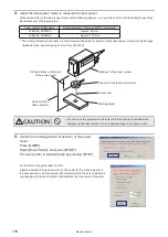
Install the laser power meter to measure the laser power.
Place the detector of the laser power meter at the following distance, i.e. one-third to half of the focal length (specified
work distance) of the laser marker.
Laser marker model name
Setting distance of detector of the power meter
LP-M500, LP-M200
Approx. 90 mm
LP-M505, LP-M205
Approx. 110 mm
* The setting distance shown above is the recommended value for detector of the laser power meter with the damage
threshold (max. power density) of more than 10kW/cm
2
.
Head part of the laser marker
Detector of the laser power meter
Laser beam
Marking object
Setting distance of detector
of the power meter
Work distance
(Base position)
CAUTION
• Do not place the power meter detector at the focal point (specified work
distance) of the laser marker. It may cause damage to the power meter.
5.
Confirm the setting position of detector of the power
meter.
Press [GUIDE].
Select [Dual Pointer], and press [START].
The dual pointer is will deactivate by pressing [STOP].
Set Z offset of the guide laser to 0 mm.
Light is received in the power meter on the center of the cross indicator in
the dual pointer mode. Never place the detector where the point indicator is
overlapping with the dot indicator, that indicates the focal point of the laser.
ME-LPM-SSM-10
Summary of Contents for LP-M Series
Page 16: ...16 MEMO ME LPM SSM 10...
Page 27: ...27 Chapter 1 Specification ME LPM SSM 10...
Page 37: ...37 Chapter 2 Preparation ME LPM SSM 10...
Page 69: ...Chapter 3 Connection for External Control ME LPM SSM 10...
Page 128: ...Chapter 4 Maintenance ME LPM SSM 10...
Page 148: ...Troubleshooting ME LPM SSM 10...
Page 169: ...Index ME LPM SSM 10...
Page 172: ...172 MEMO No 9000 0066 34V ME LPM SSM 10...
Page 173: ...No 9000 0066 34V...

