82
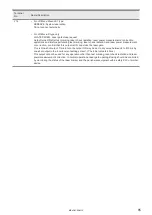
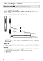
Terminal No.
Name / Description
X10
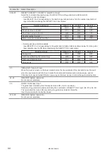
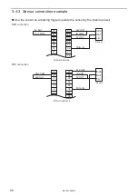
SHUTTER A: Shutter control input A
The shutter inside head is opened while the terminal remains in ON position. (The terminal control is
available during shutter control Input B ON).
There is a delay time of around 200ms to max. 1 second from turning ON/OFF of SHUTTER A/B IN for
the actual shutter open / close operation time.
This terminal is available when the DIP switch No. 2 is turned OFF.
X11
SHUTTER B: Shutter control input B
Control by the shutter control input (A) is available during shutter control input (B) ON. The input
becomes ON by short-circuiting between X11: shutter control input (B) and X12: OUT COM. Normally,
use these terminals in input ON.
WARNING
• Do not use Shutter Control Input as the interlock. If Shutter Control
input
becomes ON during laser emission, the shutter is closed after the marking
operation has been finished.
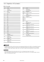
X12
OUT COM.: Output common
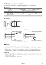
The common terminal for each output of the I/O terminal and I/O connector. Y2, X12, X15, X18 and
No. 37 of I/O connector are the common terminal connected internally. In case of NPN connection,
this terminal is connected to the “- (minus)” side of power which is used for control. In case of PNP
connection, this terminal is connected to the “+ (plus)” side of power which is used for control.
X13
ALARM RES.: Alarm reset input
The reset input for restoring the system from the alarm status.
Make sure to verify the safety by eliminating the alarm causes before turning this input ON.
The alarms caused by hardware or system error cannot be recovered by this input. In this case, restart
the laser marker.
X14
X19
X16
X17
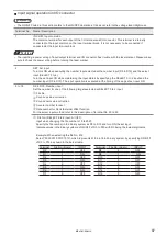
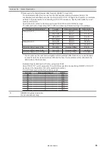
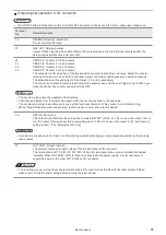
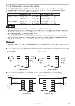
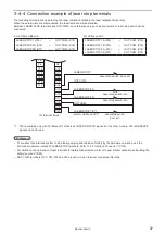
LASER STOP 1: Laser stop 1 input (LASER STOP 1A: Laser stop 1 input A at LP-Mxxx-LS1)
LASER STOP 1B: Laser stop 1 input B (Equipped only in LP-Mxxx-LS1) *1
LASER STOP 2A: Laser stop 2 input A
LASER STOP 2B: Laser stop 2 input B
Use these terminals to stop the laser radiation or disable the laser radiation temporarily.
When between either of LASER STOP terminals and OUT COM. are disconnected, the laser radiation
will be disabled.
The laser marker operates as shown below according to the terminal and its open status. For details,
refer to “Laser marker operation at inputting the safety functions” (P.25).
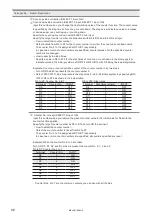
Terminal connection
Status when the terminal is open
Shutter
Laser
pumping
LASER STOP 1 (X14) - OUT COM.
LASER STOP 1B (X19) *1 - OUT COM.
Laser is not radiating
Close
Hold ON
Radiating the laser
Close
OFF
LASER STOP 2A (X16) - OUT COM.
LASER STOP 2B (X17) - OUT COM.
The same operation at all times
Close
OFF
The function relating to safety must be shut off mechanically. Therefore, it is recommended to wire these
terminal at no-voltage contact (dry contact). If you need to shut off the laser pumping physically, user the
interlock connector instead of these terminals.
X15
X18
OUT COM.: Output common
OUT COM.: Output common
The common terminal for each output of the I/O terminal and I/O connector. Y2, X12, X15, X18 and No. 37
of I/O connector are the common terminal connected internally. In case of NPN connection, this terminal
is connected to the “- (minus)” side of power which is used for control. In case of PNP connection, this
terminal is connected to the “+ (plus)” side of power which is used for control.
X19
X20
RESERVE: System reservation (except for LP-Mxxx-LS1) *1
RESERVE: System reservation
Do not connect externally.
*1 : X19 is available only with LP-Mxxx-LS1 models as LASER STOP 1B signal. For the other models, X19 is RESERVE
signal and not for use.
ME-LPM-SSM-10
Summary of Contents for LP-M Series
Page 16: ...16 MEMO ME LPM SSM 10...
Page 27: ...27 Chapter 1 Specification ME LPM SSM 10...
Page 37: ...37 Chapter 2 Preparation ME LPM SSM 10...
Page 69: ...Chapter 3 Connection for External Control ME LPM SSM 10...
Page 128: ...Chapter 4 Maintenance ME LPM SSM 10...
Page 148: ...Troubleshooting ME LPM SSM 10...
Page 169: ...Index ME LPM SSM 10...
Page 172: ...172 MEMO No 9000 0066 34V ME LPM SSM 10...
Page 173: ...No 9000 0066 34V...

